

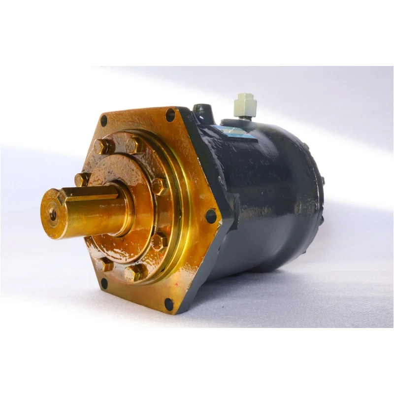
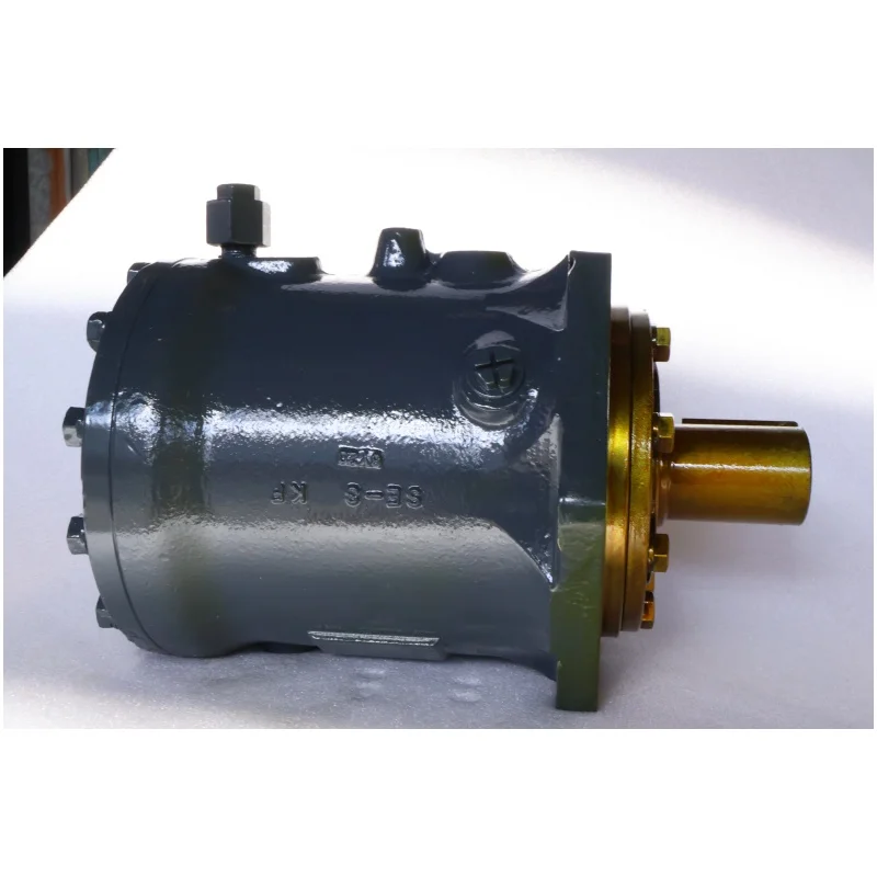

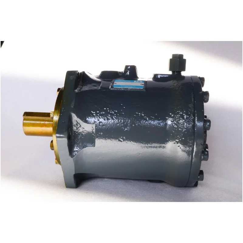


MB ME Hydraulic Motor ME100 ME150 ME175 ME300 ME350 ME600A ME750A ME850 ME1300A ME1900 ME2600 ME3100 ME4100 ME3100 Piston Motor
Basic specifications
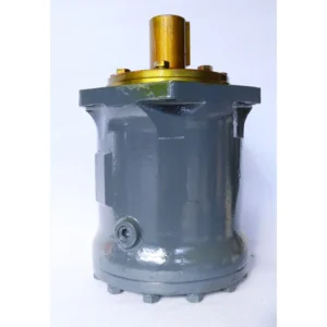
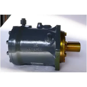
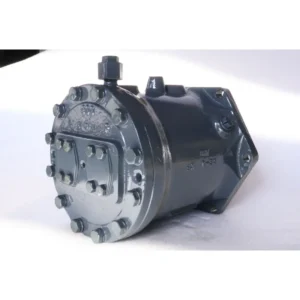
Type: Double swash plate axial piston hydraulic motor. ME indicates the series, 300 indicates the nominal displacement is approximately 300cc/rev, and BP is the special function code
Nominal displacement: 300cc/rev (output 300 milliliters of hydraulic oil per revolution), theoretical flow rate is approximately 450L/min at 1500r/min
Rated working pressure: 28MPa (280bar), short-term peak pressure up to 35MPa (350bar), suitable for high-pressure working conditions
Rated speed: 660r/min, short-term maximum speed 800r/min, minimum stable speed ≥150r/min
Output torque: 1320N · m (at 28MPa pressure), maximum peak torque approximately 1600N · m (short time)
Output power: 90kW (rated working condition), maximum up to 106kW (short time)
Rotation direction: Standard clockwise (viewed from the shaft end), some models can be optionally counterclockwise
Weight: Approximately 70kg (excluding accessories), compact structure, and high power density
Working parameters
Volumetric efficiency: ≥92% (under rated conditions), with low energy conversion loss
Overall efficiency: ≥85%, with highly efficient comprehensive performance
Applicable medium: Anti-wear hydraulic oil (viscosity index ≥90), L-HM46 or L-HV46 hydraulic oil is recommended
Medium viscosity: 10-300mm²/s, optimal working viscosity: 20-60mm²/s
Medium temperature: -20℃ to +70℃, recommended working temperature: 30-55℃
Oil cleanliness: ISO 4406 18/15 grade. A 10μm precision filter must be installed to protect the precision componentsIi. Working Principle
The core working mechanism of the double swash plate plunger motor
Structural features
It adopts a unique double swash plate design. Two sets of swash plates are symmetrically arranged on both sides of the cylinder block, at the same Angle as the cylinder block axis
Seven plunger holes are evenly distributed on the cylinder block, with one plunger installed in each hole. The plunger head is in contact with the swash plate through the sliding shoe
The oil distribution plate is fixed on the shell and is equipped with symmetrical oil suction and discharge Windows, which are respectively connected to the oil inlet and return ports
The built-in balance valve ensures that the bottom of the plunger is always under high pressure, improving low-speed stability
Principle of torque generation
High-pressure oil enters the oil distribution plate from the oil inlet and acts simultaneously on the bottom of the plunger and the working chamber
The oil pressure at the bottom of the plunger pushes the sliding shoe tightly against the swash plate, forming a sealed working chamber
Due to the double swash plate design, the force directions on both sides of the plungers are opposite at the same time, generating a combined torque
The axial force F generated by the plunger under the action of oil pressure =p×π×d²/4 (where p is the oil pressure and d is the diameter of the plunger)
The axial force is converted into the tangential force of the swash plate through the sliding shoe, thereby generating the torque T=F×r×sinα (where r is the radius of the plunger distribution circle and α is the inclination Angle of the swash plate).
The torque of the swash plates on both sides is superimposed to output a stable and large torque, with the torque fluctuation controlled within ±3%
Oil flow direction
High-pressure oil → Oil inlet → high-pressure window of the oil distribution plate → bottom of the plunger and working chamber → Push the plunger to move outward
After the cylinder block rotates 180°, the plunger reaches the other side and begins its return stroke
During the return journey, the oil pressure in the plunger chamber rises → the low-pressure window of the oil distribution plate → the oil outlet → and then returns to the oil tank
The double swash plate structure enables the motor to complete two oil suction and discharge cycles per revolution, resulting in smaller flow pulsation
Variable Principle (for some models) :
The output torque and flow rate can be controlled by adjusting the plunger stroke by changing the inclination Angle of the swash plate
When the system pressure reaches the set value, the variable mechanism automatically reduces the inclination Angle of the swash plate, limits the output torque and protects the system
The variable response time is less than 300ms, which can quickly track load changes and reduce pressure fluctuations
Iii. Product Features and Advantages
1. Outstanding output performance
High torque density: The output torque per unit volume is large, 3 to 5 times higher than that of gear motors of the same displacement, making it suitable for heavy-duty applications
Low-speed stability: It can still output the rated torque at a low speed of 150r/min without crawling, making it suitable for precise control
Smooth operation: The symmetrical design of the double swash plates results in small torque fluctuation (<±3%), low vibration and noise (<75dB).
Short-term overload capacity: It can withstand 120% of the rated pressure and torque for 10 minutes continuously, meeting the demand for sudden loads
2. Unique double swash plate structure advantage
Force balance: The symmetrical design of the double swash plates cancels out the axial forces, reducing the load on the bearings and extending their service life
Impact resistance: It can withstand an instantaneous impact of 200% of the rated pressure and adapt to harsh working conditions
Compact structure: With the same output power, its volume is 20% smaller than that of a single swash plate and its weight is 15% lighter, making it suitable for space-constrained scenarios
High reliability: The key friction pairs are made of special wear-resistant materials, with an average mean time between failures of over 8,000 hours
3. System adaptability and control characteristics
Multiple control modes: Optional pressure compensation, flow control, power control and other control modes are available to meet the requirements of different systems
Excellent self-priming ability: It can start normally without additional auxiliary pumps, and the suction lift can reach 4 meters (depending on the viscosity of the medium)
Modular design: Functional components such as brakes and buffer valves can be selected as needed to enhance system integration
Bidirectional rotation capability: Some models can be optionally equipped with a bidirectional rotation function to meet the requirements of forward and reverse rotation and simplify the system design
4. Maintenance and Economy
Easy maintenance: Modular structure, main components can be replaced separately, reducing maintenance time by 50%
Long service life: Special materials and heat treatment processes ensure that the key friction pairs have a service life of over 10,000 hours
Energy consumption optimization: Automatically reduces the displacement under light load conditions, achieving significant energy-saving effects and lowering the operating costs of the system
Iv. Usage Functions and Purposes
Core functions
Convert the pressure energy of the hydraulic system into mechanical energy to provide rotational power
Precisely control the output torque and rotational speed to meet the requirements of different working conditions
In coordination with the hydraulic control system, it realizes the automated production process
Main application fields
Walking drive for construction machinery
Chassis walking systems for excavators, loaders, bulldozers, etc
It provides stable traction and climbing ability, adapting to complex terrains
It provides smooth transitions when switching between high and low speeds and turning, reducing shock
Hoisting and lifting mechanism
Hoisting systems for cranes, tower cranes and port machinery
It provides a large torque lifting force to ensure safety and stability under heavy load conditions
It works in conjunction with the brake to achieve precise position control and safe braking
Rotary mechanism
The rotary platform drive of excavators, drilling RIGS and ship deck machinery
Achieve smooth and precise 360° rotation with high positioning accuracy
Maintain stable output under wind load and wave load
Industrial application
Injection molding machine clamping device, press drive system
Provide stable high pressure and precise position control to ensure product quality
The transmission systems of metallurgical equipment and mining machinery are suitable for harsh environments
Ship and Ocean Engineering
Servo system, anchor machine, winch drive
Provide reliable power in damp and salt spray environments
Adapt to the swaying conditions of ships and maintain stable output
V. Applicable Machines and Scenarios
1. Typical applicable machines
Excavator walking system
It is particularly suitable for excavators of 15 to 30 tons, such as the PC200 and ZX210 models of a certain brand
As a walking motor, it provides strong traction and climbing ability, with a maximum climbing Angle of up to 30°
When performing compound actions, it coordinates and cooperates with the working device to increase the overall efficiency of the machine by 15-20%
Port crane
It is applicable to the hoisting and slewing systems of tyre cranes and portal cranes
It provides stable power under frequent start-stop and heavy load conditions to ensure the safe loading and unloading of goods
In combination with the variable frequency hydraulic system, precise position control can be achieved, with a positioning accuracy of ±5mm
Injection molding machine clamping device
Provide stable clamping force for injection molding machines with a clamping force of 1,000 to 2,000 tons
During the pressure-holding stage, the flow rate is automatically reduced, saving 50-70% of energy while maintaining a stable pressure
Ensure that the mold closes evenly to prevent defects such as flash and deformation in plastic products
2. Characteristics of applicable scenarios
Construction machinery and industrial equipment that require high torque output, especially under low-speed and heavy-load conditions
Precision control equipment that requires smooth operation and low noise, such as precision machine tools and robots
It can adapt to high-temperature, humid and dusty environments in harsh working conditions such as mining, metallurgy and shipping
The working device of construction machinery that requires frequent start-stop and reversing responds quickly and has little impact
In medium and high-pressure application scenarios where the hydraulic system pressure is stabilized at 20-30 mpa, its high-pressure performance can be fully exerted
Six. Similar models
1. Different specifications and models of the same series
ME350BC: Displacement 350cc/rev, output torque 1520N · m, power 106kW, suitable for construction machinery and Marine equipment with larger loads
ME750: Displacement 750cc/rev, output torque 3500N · m, power 250kW, suitable for super-heavy equipment such as large excavators and shield machines
ME1300: Displacement 1300cc/rev, output torque over 6000N · m, power over 400kW, suitable for large-scale mining machinery and Marine engineering equipment
2. Different series models of the same type
MB300BP: With the same displacement as ME300BP, but with different bearing configurations and sealing forms, it is suitable for more severe Marine environments
ME300BC: Basically the same as ME300BP, but with a brake (BC indicates with a brake), suitable for winch systems that require emergency braking
A2F300: A certain brand of quantitative plunger motor with no variable function, suitable for application scenarios that require constant speed
3. Domestic alternative products
Domestic ME300 series alternatives: For instance, the 300cc/rev double swash plate plunger motor produced by a certain brand has similar performance parameters but is more economical in price, making it suitable for the domestic maintenance market
Other brands of 300cc grade hydraulic motors, such as YMD300 and BMR300, can be used as substitutes under specific conditions, but their performance may vary slightly
Vii. Precautions for Use
1. Installation points
Direction confirmation
It must be installed in the specified direction (standard clockwise). The oil inlet and return ports must not be connected in reverse; otherwise, the internal seal and oil distribution mechanism will be damaged
Fixation and connection
The installation plane must be flat (flatness < 0.1mm), and the fixing bolts should be evenly tightened to prevent the shell from deforming and affecting the movement of the plunger
The output shaft and the load must be connected by an elastic coupling. Rigid connection is strictly prohibited
Coaxiality error is less than 0.05mm, angular deviation is less than 0.5°, reducing vibration and bearing load
Pipeline configuration
The diameter of the oil inlet pipe should be no less than 50mm and the length less than 2m to reduce oil suction resistance and prevent cavitation
The diameter of the oil outlet pipe should be ≥40mm to ensure smooth oil return and a back pressure of less than 0.5MPa
The oil drain pipe must be led back to the oil tank separately and not connected to back pressure to ensure the smooth discharge of the leaked oil inside
2. Startup and Operation management
Startup program
Check the oil level in the fuel tank (≥ 300mm above the suction port) and the oil temperature (≥-10℃)
Manually turn the wheel 2 to 3 times to ensure there is no jamming
Loosen the exhaust plug, jog the start motor to exhaust, and then tighten it after continuous oil output
Start the machine without load and run it for 5 to 10 minutes to observe if there are any abnormal noises or leaks
Gradually load (each time ≤30% of the rated pressure, with an interval of ≥2 minutes). It is strictly prohibited to directly load the cold machine to full capacity
Operation monitoring
Oil temperature: Normal operating temperature is 30-55℃. If the temperature exceeds 70℃, the machine should be shut down to check the cooling system
Pressure: Not exceeding the rated value (28MPa), peak not exceeding 35MPa and cumulative time less than 10 minutes per hour
Noise: Smooth operation <75dB. Abnormal noise (>80dB) indicates possible wear or cavitation, and the machine should be stopped immediately
Leakage: Slight seepage (<10 drops per minute) is allowed. If the leakage increases, timely maintenance is required
3. Maintenance and care
Daily inspection
Check the oil level, temperature, noise and leakage conditions every shift, and record the operating parameters
Check if the connecting bolts are loose and tighten them in time
Clean the surface of the motor to prevent the accumulation of oil stains from affecting heat dissipation
Regular maintenance
Every 250 hours: Check the pressure difference of the filter (<0.15MPa), and replace the filter element if necessary
Every 500 hours: Check the contamination level of the oil (≤ISO 4406 18/15 grade), and take samples for testing if necessary
Every 1000 hours: Change the hydraulic oil and clean the oil tank and filter at the same time
Every 2000 hours: Comprehensive disassembly and inspection, measurement of key fit clearances, and replacement of worn parts (such as plungers and sliders)
Oil Product management
Hydraulic oils of different brands must not be mixed to prevent the reaction of additives and the formation of sediment
In cold regions, low-viscosity hydraulic oil (such as L-HV series) should be used to ensure low-temperature starting performance
Regularly test the viscosity and acid value of the oil to ensure they meet the usage requirements
4. Special Precautions
Prevent dry running
It is strictly prohibited to start the motor without oil. Even a short period of dry running will cause severe wear of the plunger and swash plate
After a long period of inactivity, when restarting the motor, clean hydraulic oil should be filled into it
Prevent cavitation
Ensure that the oil suction pipeline is well sealed to prevent air from entering the system and forming bubbles
The oil suction height should be less than 500mm, and it is recommended to be less than 300mm to reduce the oil suction resistance
When the oil temperature is too low (<10℃), run it no-load for 15 minutes first to increase the oil temperature before loading
Load matching
It is strictly prohibited to operate beyond the rated pressure and speed; otherwise, the service life will be significantly shortened
Avoid frequent overload impacts and protect the precision mating parts inside the motor
Theoretically, it is not allowed for the maximum torque and the highest rotational speed to occur simultaneously to avoid overload
Shutdown protection
Before shutting down, the oil should be unloaded to a low pressure (<20bar) and run for 3 to 5 minutes. Only when the oil temperature drops below 60℃ should the power be cut off
When the motor is not in use for a long time, the oil inlet and outlet ports should be sealed to prevent foreign objects from entering the interior


