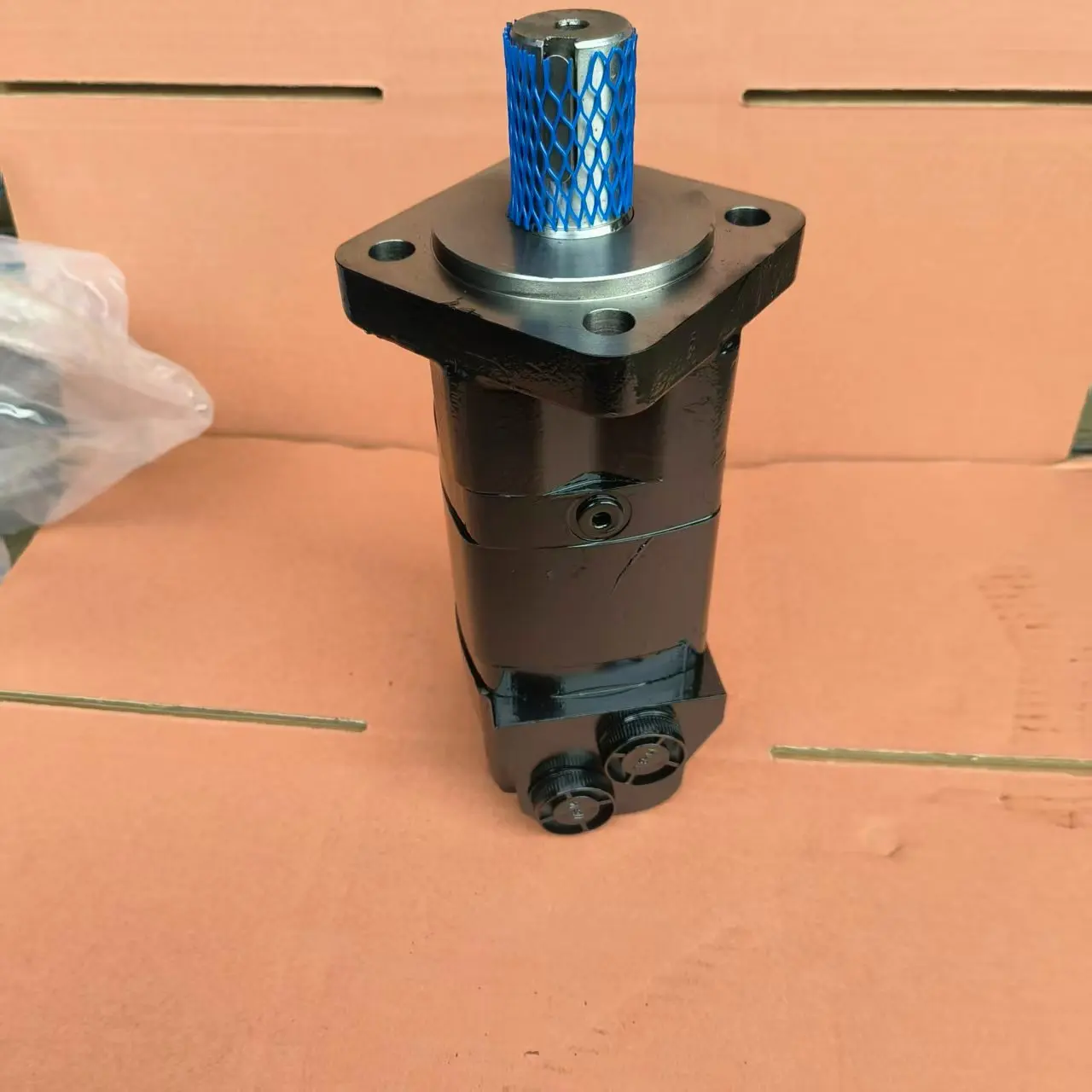
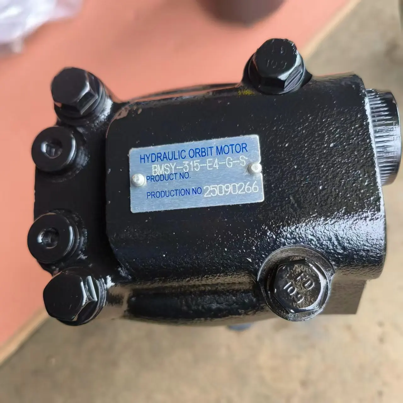
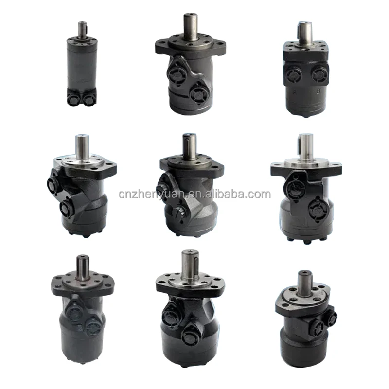
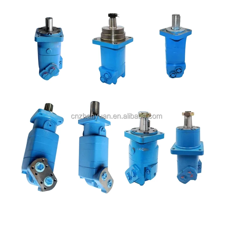
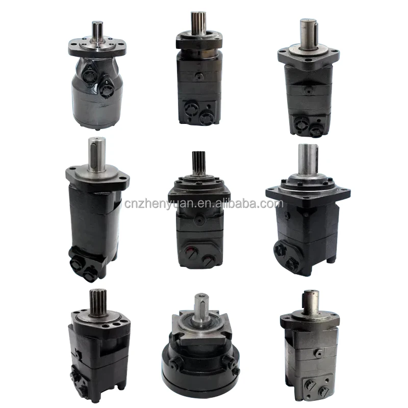

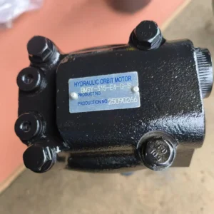
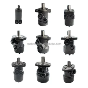

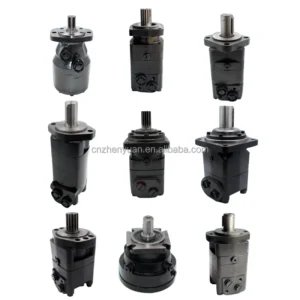
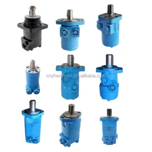
Orbit Piston Motor BMSY-80 BMSY-125 BMSY-160 BMSYS-250 BMSYS-200 Cycloid Hydraulic Motor BMSY-315-E4-G-S
Core performance parameters
– Motor type: End face distribution cycloidal hydraulic motor, columned rotor-stator structure, clockwise/counterclockwise bidirectional rotation, suitable for medium and high-pressure hydraulic circuits, core low-speed high-torque power output, specially designed for heavy-duty actuators.
– Displacement and torque parameters: Rated displacement 315 mL/r; Rated working pressure: 20 MPa, maximum allowable pressure: 22 MPa (short-term ≤10 seconds); Rated speed: 150 r/min, maximum speed: 240 r/min (short time ≤5 minutes); Rated torque: 900 N·m, peak torque: 1000 N·m.
– Flow rate and efficiency parameters: Flow rate 47 L/min at rated speed, maximum flow rate 60 L/min; Volumetric efficiency ≥90%, total efficiency ≥85%; The starting pressure is ≤1.5 MPa, and the low-speed stability error is ≤5% (at 50 r/min).
– Operating characteristics: Continuous operating oil temperature ≤80℃, maximum allowable oil temperature 90℃; Noise value ≤78 dB (measured at 1 meter); The fault-free operating life under rated conditions is ≥ 8,000 hours.
2. Structure and connection parameters
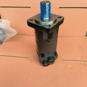
– Structural type: It adopts a cycloidal pinwheel meshing pair with a small tooth difference (6 teeth for rotor and 7 teeth for stator), integrates an end face distribution plate, tapered roller bearings and an internal buffer valve. The output shaft is designed with A key connection and is equipped with an SAE”A” type four-bolt flange installation structure, supporting both axial and radial load bearing.
– Core material: The rotor and stator are alloy structural steel (quenched and tempered, hardness HRC58-62); The distribution plate is made of bronze alloy (with graphite self-lubricating). The output shaft is 40CrNiMoA (quenched treatment). The sealing part is a high-pressure resistant fluororubber combination (temperature resistance ≤120℃).
– Connection specifications: Both the oil inlet (P) and the oil return (T) are 7/8-14 SAE threads. The output shaft is a 1.25-inch key shaft. Install flange bolts with a center distance of 100×80 mm. The motor weighs approximately 45 kg, and its external dimensions (length × width × height) ≈380×260×320 mm.
3. Medium and Environmental requirements
– Medium requirements: L-HM 46/68 anti-wear hydraulic oil is suitable for normal temperature, and L-HM 32 is selected for low-temperature environment; The allowable viscosity of the medium is 100-400 SUS (approximately 20-80 mm²/s), and the moisture content is ≤0.05%. It is strictly prohibited to use media containing solid particles (particle size > 10 μm) or corrosive media.
– Cleanliness standard: The oil cleanliness should reach ISO 4406 18/13 grade. It is recommended to install a 10 μm fine filter in front of the motor oil inlet. Replace the filter immediately when the pressure difference of the filter is greater than 0.1 MPa.
– Environmental parameters: Operating environment temperature -20℃ to 80℃, relative humidity ≤95% (short-term condensation is allowed); With a protection grade of IP65, it is suitable for dusty and humid construction machinery, mining and industrial scenarios.Ii. Working Principle
This motor is an end face distribution cycloidal hydraulic motor. Its core converts hydraulic energy into mechanical energy through the mechanism of “cycloidal meshing volume change – planetary motion power conversion – synchronous distribution”. The specific process is as follows:
1. Core process of power conversion
High-pressure oil enters the motor through the oil inlet and is precisely distributed to the sealed cavity formed by the meshing of the rotor and stator through the end face distribution plate. The stator remains stationary. The rotor and stator mesh with cycloidal pinwheel teeth with a small tooth difference (1 tooth difference). Under the drive of high-pressure oil, the rotor simultaneously performs two movements: one is a low-speed self-rotation around its own axis, and the other is a high-speed reverse revolution around the center of the stator. The self-rotation motion of the rotor is transmitted to the output shaft through a drum-shaped spline coupling, driving the load to rotate. During the revolution, the sealed cavity continuously completes the volume change cycle of “high-pressure oil suction – low-pressure oil discharge”.
2. Distribution and steering control
– Synchronous distribution mechanism: The distribution plate rotates synchronously with the output shaft. The oil inlet and return states of the sealed cavity are switched in real time through the oil grooves distributed alternately on the surface, ensuring that the high-pressure cavity is always on the force-bearing side of the rotor and the low-pressure cavity is on the volume contraction side, achieving continuous and stable output.
– Steering adjustment: By changing the direction of oil intake and return, it can rotate in the opposite direction. It is also possible to achieve steering switching when the oil inlet and return ports remain unchanged by adjusting the installation phase of the distribution plate and the spline coupling (offset by one tooth), to meet different operational requirements.
Iii. Product Features and Advantages
– Strong low-speed and high-torque adaptability: With a large displacement of 315 mL/r and a working pressure of 20 MPa, the rated torque reaches 900 N·m. Even at a low-speed of 150 r/min, it can still stably output heavy-load power. It can directly drive medium and heavy-duty loads without additional reduction mechanisms and is suitable for actuators of equipment ranging from 20 to 50 tons.
– Outstanding high pressure resistance and load-bearing capacity: It adopts a cylindrical rotor and stator design and a tapered roller bearing structure. The end face distribution plate has an automatic wear compensation function, and the volumetric efficiency at the rated pressure is ≥90%. The output shaft can withstand high axial and radial loads and is suitable for direct connection to the working mechanism without the need for intermediate supports.
– High efficiency, long life and stable operation: The precise meshing of the rotor and stator, combined with self-lubricating materials, reduces friction and wear. The built-in buffer valve reduces pressure shock (≤1.2 MPa), the starting pressure is ≤1.5 MPa, and there is no crawling phenomenon during low-speed operation. The rated working condition fault-free life is ≥ 8,000 hours, which is 20% longer than that of ordinary cycloidal motors.
– Compact, reliable and easy to maintain: Integrated structure design, weighing only 45 kg, saves 30% of installation space compared to gear motors of the same torque. The vulnerable parts (seals, distribution plates) have strong versatility. They can be disassembled and replaced without special tools. Daily maintenance only requires regular checks on the cleanliness of the oil.
Iv. Usage Functions and Purposes
1. Core usage functions
– Heavy-duty drive function: It provides high-torque power for low-speed rotating actuators, suitable for actions such as “rotation – swing – walking”, such as the rotation of construction machinery, track walking, stirring and winding of industrial equipment, etc. It can directly replace the combination of a reduction motor and a common motor.
– Load holding function: The end face distribution structure has good sealing performance. When the machine stops, the leakage is ≤3 mL/min, which can achieve long-term static load holding (such as crane boom hovering). When combined with a balance valve, the pressure holding stability can be further enhanced.
– Harsh working condition adaptation function: With an IP65 protection rating, it can withstand harsh environments such as dust and spray. Wide-temperature oil adaptability (-20℃ to 90℃), meeting the operational requirements of various scenarios such as outdoor, mining, and port operations.
2. Main application fields
In the field of construction machinery: 20-50 ton crawler excavator slewing mechanisms, 20-30 ton wheel loader traveling systems, small bulldozer drive axles, suitable for heavy-duty operations such as urban and rural infrastructure construction and mining.
– Industrial and special fields: Underground mine car drive in mines, winch of cranes under 30 tons in ports, drive of concrete mixing tanks, push head power for garbage compression equipment, suitable for continuous heavy-load or intermittent high-intensity operations.
In the fields of agriculture and environmental sanitation: Large combine harvester track drive, 3-5 cubic meter garbage truck compaction mechanism, high-pressure cleaning vehicle reel drive, suitable for outdoor dusty and humid mobile operation scenarios.
V. Applicable Machines and Scenarios
1. Adapt to the core machine
– Construction machinery: 20-50 ton crawler excavators, 20-30 ton wheel loaders, small bulldozers, and truck cranes under 30 tons.
– Industrial equipment: Small underground mine cars for mines, concrete mixing tanks, small winches for ports, heavy-duty winding machines.
– Special equipment: Large combine harvesters, 3-5 cubic meter garbage compsors, high-pressure cleaning vehicles, small crawler-type exploration equipment.
2. Typical application scenarios
– Excavator rotation scenario: As a 30-ton excavator rotation motor, it outputs a torque of 900 N·m to drive the rotation platform, achieving smooth steering at a speed of 150 r/min. Combined with a buffer valve, it reduces the start-stop impact, making it suitable for high-frequency rotation operations during hard rock excavation in mines. It can work continuously for 8 hours a day without failure.
– Mixing tank drive scenario: It is equipped with a 6-cubic concrete mixing tank, with an output torque of 800 N·m to drive the tank to rotate at a low speed of 15-20 r/min. The end face distribution structure ensures that the speed fluctuation is ≤3%, making it suitable for continuous mixing operations on construction sites. When the oil cleanliness meets the standards, the service life can reach 10,000 hours.
– Garbage truck compaction scenario: Drive the 4-cubic-meter garbage truck compaction push head. Output 950 N·m torque under 20 MPa pressure to achieve compaction action. IP65 protection to resist garbage seepage and dust erosion. It can start normally in a winter environment of -10℃, meeting the all-weather operation requirements of environmental sanitation.
Six. Similar models
1. Alternative models of the same series
-BMSY-250-E4-G-S: A small-displacement model of the same structure, with a rated displacement of 250 mL/r and a rated torque of 700 N·m. The pressure parameters are consistent. It is suitable for 10-20 ton class light equipment (such as 20-ton excavator rotation), and the cost is 22% lower than that of the original model.
-BMSY-400-E4-G-S: A large-displacement model in the same series, with a rated displacement of 400 mL/r and a rated torque of 1100 N·m. The pressure parameters are the same. It is suitable for heavy equipment of 50-80 tons (such as 50-ton loader travel), but the cost is 30% higher than that of the original model.
2. Cross-series alternative models
-BMSY-315-E4-G-B: Model with brake, integrated spring braking mechanism, automatically locks the output shaft when power is off (static braking torque 1800 N·m), suitable for scenarios requiring safety locking such as crane winches and elevator lifting. The cost is 45% higher than that of the original model.
-BMSY-315-E5-G-S: A high-pressure upgraded model with a rated pressure of 25 MPa and a rated torque of 1100 N·m. The structure is basically the same and it is suitable for high-pressure working conditions such as metallurgy and heavy forging. The cost is 35% higher than that of the original model.
-BMSY-315-E4-G-F: Flange variant model, installed with international standard flanges, suitable for the replacement scenarios of imported equipment, with the same parameters as the original model and the same cost.
Vii. Precautions for Use
1. Medium management
At normal temperature, L-HM 46/68 anti-wear hydraulic oil should be selected. At low temperature (below -10℃), L-HM 32 should be selected. It is strictly prohibited to mix oils of different grades. Before the new motor is used for the first time, the pipeline should be flushed with clean oil in circulation for ≥20 minutes to ensure that the cleanliness meets ISO 4406 18/13 grade.
– Check the pressure difference of the oil inlet filter weekly (replace the filter element when it exceeds 0.1 MPa), test the moisture content of the oil monthly (≤0.05%), and take samples to test the cleanliness quarterly. When the oil is found to be emulsified, discolored or containing metal filings, stop the machine immediately to change the oil and disassemble and clean the inner cavity of the motor.
2. Installation and commissioning
When installing, confirm the oil inlet and return port markings (P for oil inlet and T for oil return), and it is strictly forbidden to connect them in reverse. The output shaft is connected to the load by an elastic coupling, with a coaxiality error of no more than 0.1mm. The flange bolts should be evenly tightened with a torque of 150 N·m to avoid uneven loading.
Before debugging, manually turn the wheel 3 to 5 times to confirm there is no jamming. When starting for the first time, run it at a low speed (50 r/min) without load for 1 hour (load ≤30% of the rated torque), then gradually increase the speed to the rated speed and load, and check the stability of the torque output and the leakage situation.
For outdoor installation, a rain and dust cover must be added to ensure that the protection level remains at IP65. A heat dissipation space of ≥ 50mm should be reserved on the motor surface. When working continuously, the oil temperature should be controlled within 80℃. If it exceeds this limit, a cooler needs to be installed.
3. Operation and Maintenance
During operation, real-time monitoring of motor temperature (normal ≤80℃, maximum ≤90℃), noise and leakage is conducted. If the temperature rises sharply by more than 15℃, the noise exceeds 85 dB or the leakage is greater than 5 mL/min, stop the machine immediately for inspection, with a focus on checking for oil contamination, wear of the distribution plate or damage to the bearings.
– Regular maintenance every 5,000 hours: Disassemble and clean the meshing surface of the rotor and stator and the distribution plate, and check the wear of the tooth surface (replace when the wear is greater than 0.2mm). Replace the sealing parts and bearings, reassemble and conduct an air tightness test (no leakage at 20 MPa pressure). Calibrate the current distribution phase to ensure correct steering.
It is strictly prohibited to operate under long-term overpressure (> 22 MPa) or at excessive speed (> 240 r/min). When there is a sudden change in load, the pressure shock should be controlled to be ≤25 MPa to avoid damage to the rotor and stator due to rigid shock. Before shutting down, first run at low speed without load for 5 minutes. Wait until the oil temperature drops below 60℃ before cutting off the power.
4. Storage protection
When stored for a long time, use a special plug to seal the oil inlet and return ports, inject anti-rust oil (with a viscosity of 46 mm²/s) into the motor cavity, and apply lithium-based grease to the keyway of the output shaft. Store in a dry warehouse with a temperature ranging from 0 to 40℃ and a humidity of no more than 60%. Avoid direct sunlight and heavy object compression. Manually turn the machine once a month to prevent component adhesion.
Before putting it into use after being idle for more than 12 months, thoroughly clean the inner cavity and replace the sealing parts. After circulating and flushing with low-pressure oil (5 MPa), conduct a low-speed no-load test run for 1 hour. Only after confirming no leakage and normal rotation can it be connected to the system.


