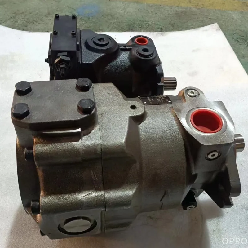
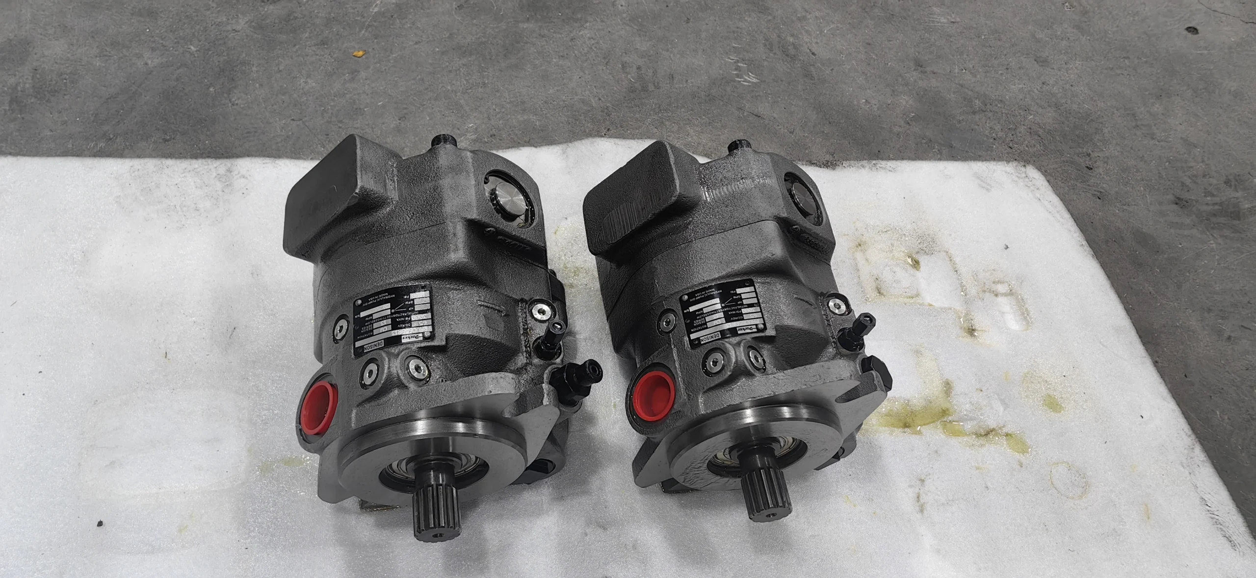
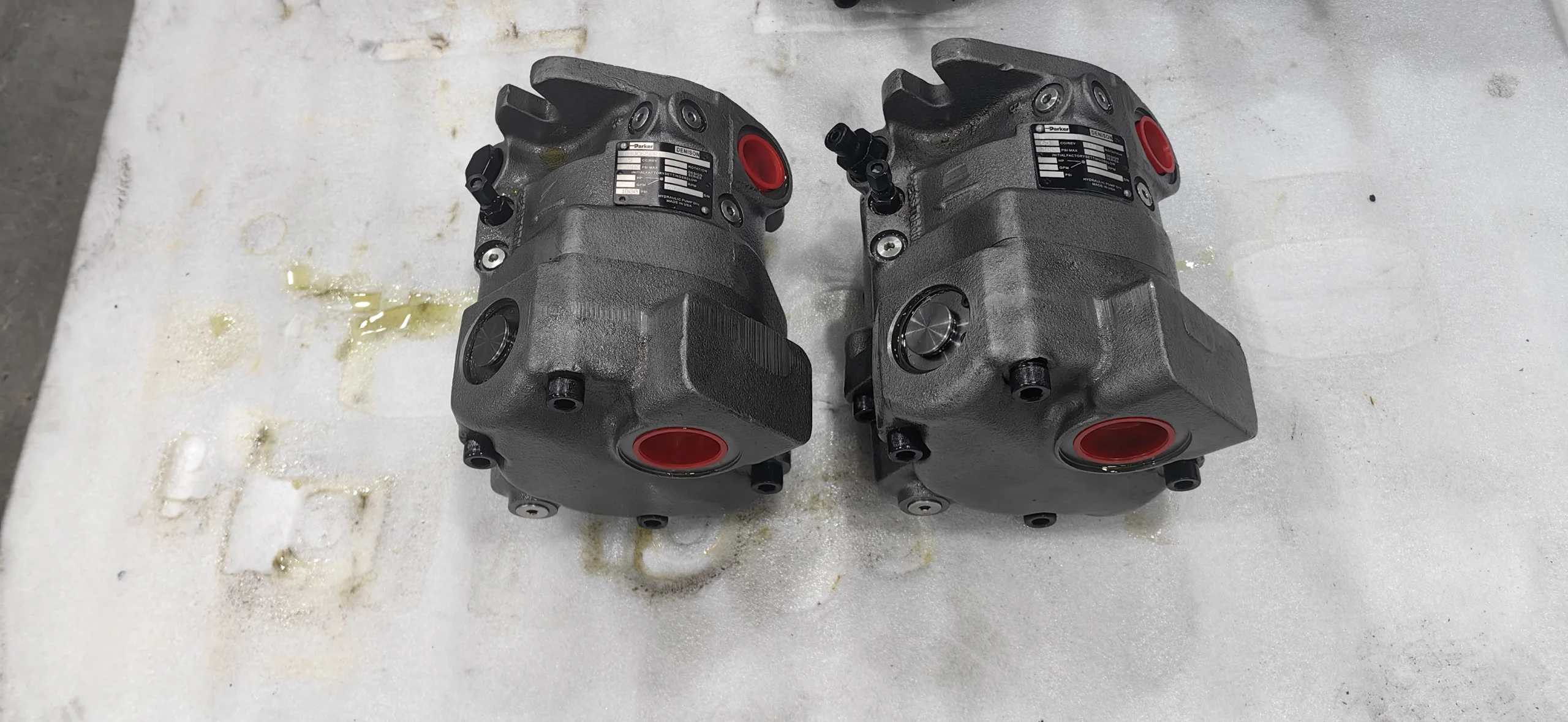
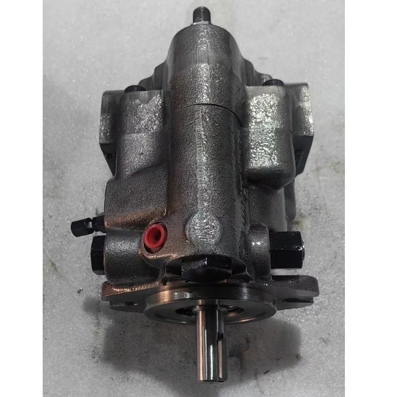
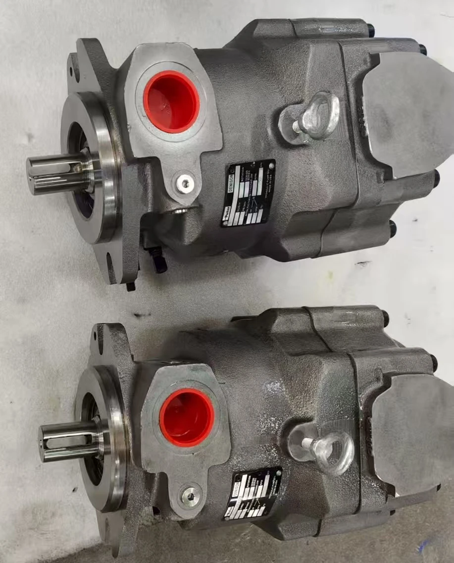
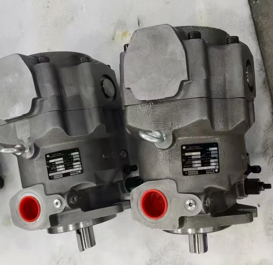


PAVC Hydraulic Pump PAVC33 PAVC38 PAVC65 PAVC100 Series PAVC65BR13 Parker High Pressure Axial Variable Piston Pump
1. Displacement: The theoretical displacement is 65 mL/r, which belongs to the medium and high pressure large flow specification and is suitable for the requirements of medium and heavy-duty hydraulic systems.
2. Work pressure:
Continuous working pressure: 207 bar (20.7 MPa)
Intermittent peak pressure: 248 bar (24.8 MPa), strong short-term overload capacity, capable of handling sudden high loads.
3. Speed range: Rated speed 3000 rpm, maximum speed up to 3000 rpm, minimum stable speed ≥500 rpm, compatible with both high-speed continuous operation and low-speed smooth operation.
4. Control Mode: It integrates dual control of load sensitivity (LS) and pressure compensation, supports electro-hydraulic proportional regulation (the BR13 mark corresponds to the electro-hydraulic proportional control module), and can dynamically adjust the displacement in real time according to the system load to achieve precise matching of flow and pressure.
5. Structural form: Swash plate axial piston structure, single cylinder block multi-piston configuration, high-strength cast iron shell, key friction pairs (such as distribution plates) made of bronze composite materials, with excellent wear resistance.
6. Oil requirements:
Applicable viscosity: Anti-wear hydraulic oil with a viscosity of 15-400 mm²/s (recommended: 20-200 mm²/s)
Working oil temperature: -40℃ to 71℃. The oil cleanliness should reach ISO 16/13 grade (NAS 8 grade).
7. Installation and Adaptation
◦ Shaft end: Flat key connection, shaft diameter complies with ISO 3019-2 standard
◦ Flange: SAE B 2 bolt or 4 bolt flange installation, oil port supports side or rear arrangement, can be installed horizontally or vertically.Ii. Working Principle
This plunger pump adopts a swashplate axial plunger structure. The core components include the drive shaft, cylinder block, plunger, swashplate and load-sensitive control valve group. At work:
1. Oil absorption process: The prime mover drives the drive shaft to rotate the cylinder block. Under the action of centrifugal force and the return disc, the plunger tightly adheres to the swash plate. When the plunger rotates to the lower side area of the swash plate, it extends outward, increasing the volume of the cylinder block’s sealed cavity and creating a vacuum. The oil then enters the cavity through the oil suction port of the distribution plate.
2. Oil pressure process: When the plunger rotates to the high side area of the swash plate, the swash plate squeezes the plunger inward, reducing the cavity volume and increasing the oil pressure. The oil is then discharged to the system through the oil outlet of the distribution plate.
3. Load sensitive control: The pressure sensor detects the system load in real time. When the load increases, the control valve group increases the inclination Angle of the swash plate, extends the plunger stroke, and enhances the displacement. When the load decreases, the inclination Angle of the swash plate decreases, and the displacement decreases simultaneously, achieving a dynamic match between the flow rate and the load and reducing energy loss.
4. Pressure compensation protection: When the system pressure reaches the set threshold, it automatically limits the increase in displacement to prevent overpressure from damaging components.
Iii. Product Features and Advantages
1. Strong adaptability to high pressure and large flow rate: The combination of 207 bar continuous pressure and 65 mL/r displacement can stably output medium and high pressure power, making it suitable for medium and heavy equipment such as 20-30 ton class construction machinery.
2. Excellent performance in high efficiency and energy conservation
The volumetric efficiency is ≥94%, and the total efficiency is ≥90%
Load sensitive control reduces energy waste in “high flow and low load” scenarios, lowering system temperature rise by more than 15%.
3. Anti-pollution and high reliability:
The optimized design of the gap seal and the use of wear-resistant materials (such as bronze distribution plates) enhance the resistance to particle contamination. Under dusty conditions, the service life can reach over 6,000 hours.
The high-strength cast iron shell and the built-in turbocharger enhance the structural rigidity, adapting to severe vibration and shock.
4. Rapid control response: The electro-hydraulic proportional control response time is ≤0.3 seconds, and the displacement adjustment range is 5%-100%. It can quickly adapt to load fluctuations and ensure the coordination of the actions of multiple actuating elements.
5. Good maintenance convenience: The modular pump core design supports the individual replacement of worn parts, and the key seals are standardized, resulting in low maintenance costs.
Iv. Usage Functions and Purposes
1. Usage function:
As the power source of the hydraulic system, it converts mechanical energy into hydraulic energy to drive hydraulic cylinders and hydraulic motors to achieve linear or rotational motion.
Through load sensitivity and pressure compensation control, dynamic flow distribution and pressure protection for multiple actuating elements are achieved, enhancing the stability and safety of the system.
2. Usage
◦ Construction machinery: Excavators, loaders, and cranes’ digging, lifting, and slewing mechanisms.
◦ Industrial equipment: injection molding machines, hydraulic presses, roller drive systems for metallurgical production lines.
◦ Mining and port machinery: Hoisting and luffing mechanisms for mine roadheaders and port handling equipment.
V. Applicable Machines and Scenarios
1. Applicable machines
Excavators of 20-30 tons, medium-sized loaders and crawler cranes.
800-1200 ton injection molding machines, 300-500 ton hydraulic presses.
Port container handling machines, mining tunneling equipment.
2. Applicable scenarios:
High-pressure and high-flow, medium and heavy load working conditions, such as earthwork excavation, material handling, and metal stamping.
Scenarios where multiple actuating elements work in coordination and the load fluctuates greatly, such as factory automated production lines and continuous loading and unloading operations at ports.
Six. Similar models
1. Same series models:
◦ PAVC33: Displacement 33 mL/r, suitable for small flow medium and high pressure systems.
◦ PAVC38: Displacement 38 mL/r, control method consistent with PAVC65, suitable for medium-load equipment.
◦ PAVC100: Displacement 100 mL/r, high-flow model, suitable for heavy-duty hydraulic systems.
2. Similar alternative models:
◦ A series 110 displacement plunger pumps (such as A110-30) : They have the same structural principle, with a rated pressure of 31.5 MPa, and are suitable for higher pressure requirements.
◦ Other brands of swash plate axial piston pumps (such as the A4VSO series) : Their performance parameters are similar, and they can be selected based on the installation interface and control requirements.
Vii. Precautions for Use
1. Oil Management Specifications:
Select hydraulic oil strictly in accordance with the requirements and avoid mixing oils of different brands or grades.
Install a ≥100 μm screen filter at the oil suction port and a 25 μm fine filter on the return oil line. Check the filter element every 500 hours and replace the hydraulic oil and clean the oil tank every 2000 to 3000 hours.
2. Installation accuracy requirements:
The prime mover is connected by an elastic coupling, with the coaxiality error of the two shafts being no more than 0.1mm and the angular error no more than 0.5°, to prevent excessive radial force from damaging the bearings.
The length of the oil suction pipeline should be no more than 1.5m, and its diameter should not be less than the suction port of the pump to reduce the risk of cavitation.
3. Startup and Operation Monitoring:
Before the first start, fill it with clean oil and manually turn the wheel 3 to 5 times to ensure there is no jamming.
After startup, run at low speed without load for 10 minutes. When the oil temperature rises above 30℃, gradually increase the load to the rated pressure.
During operation, monitor the oil temperature (30-70℃ is the best) and pressure (long-term overpressure is strictly prohibited). If any abnormality occurs, stop the machine immediately for inspection.
4. Maintenance and upkeep nodes
Check the sealing condition of the shaft seal every 1000 hours. Replace the seal when the leakage is greater than 3 drops per minute.
Disassemble and inspect the distribution plate, plunger and other friction pairs every 3,000 hours. If the wear exceeds 0.03mm, repair or replacement is required.
Before long-term shutdown, drain the oil or inject anti-rust oil, and seal the oil port to prevent impurities from entering.
5. Control parameter setting:
The parameters of the load sensitive valve and the pressure compensation valve should be adjusted by professionals according to the working conditions. It is strictly prohibited to arbitrarily increase the pressure or flow limit values.
After replacing the control module, the parameters need to be calibrated to ensure that the signal matches the displacement linearly and to avoid system shock.


