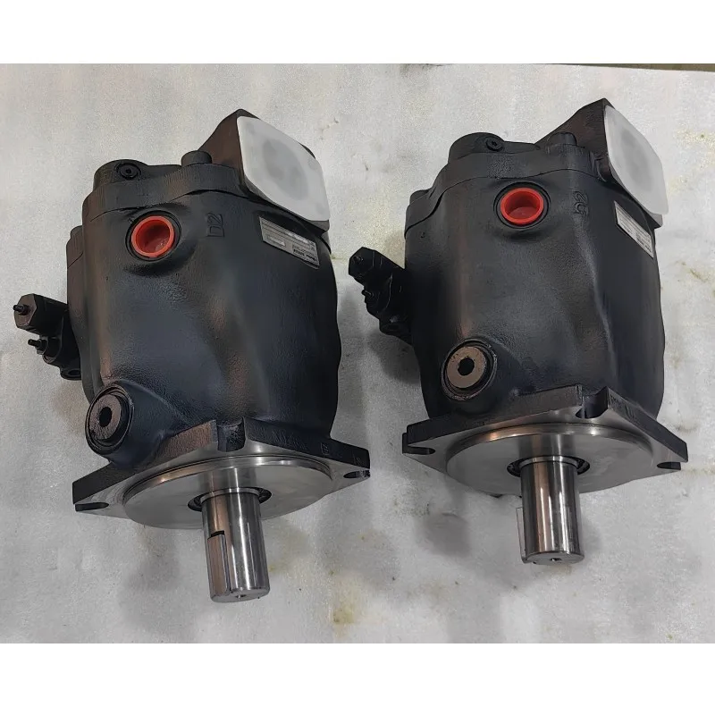

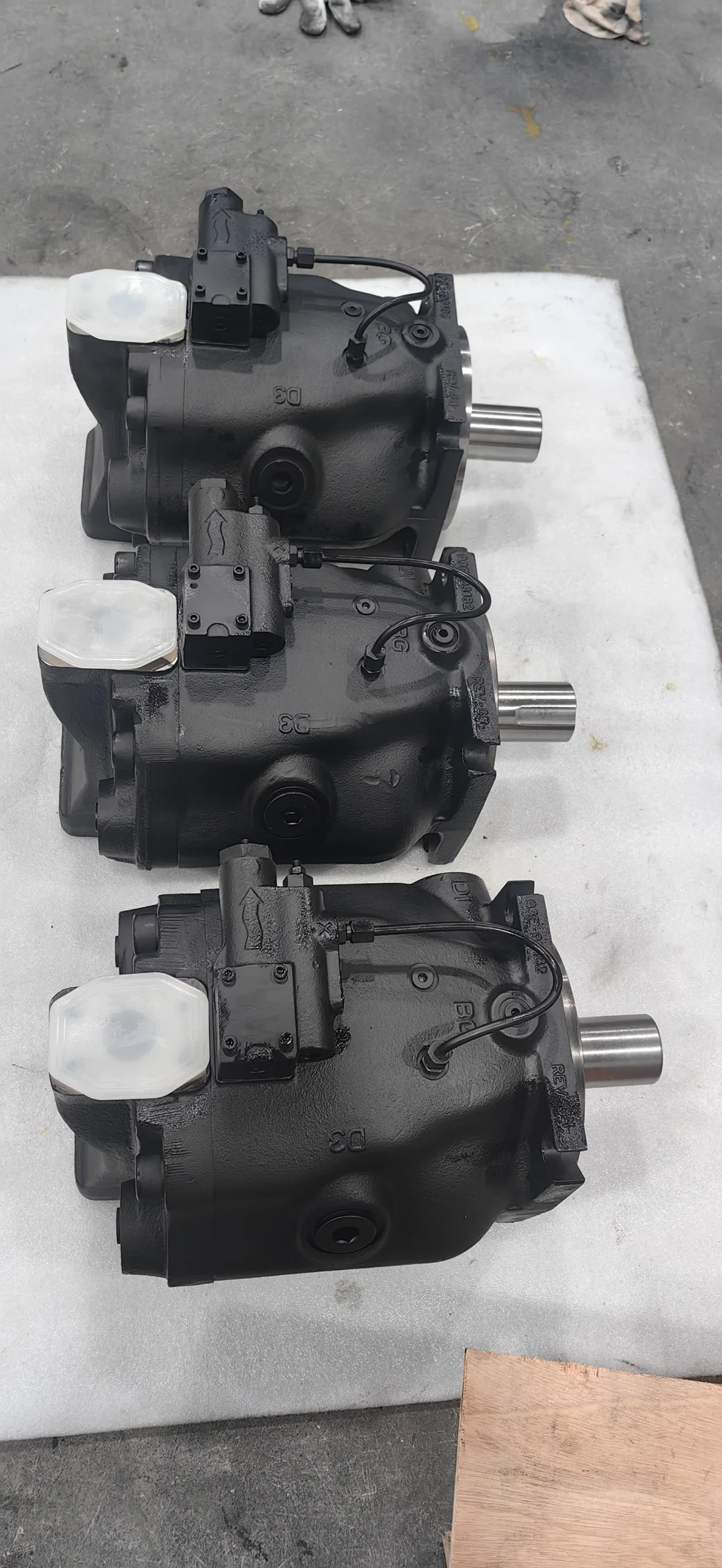

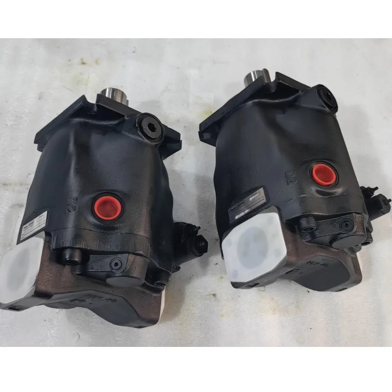
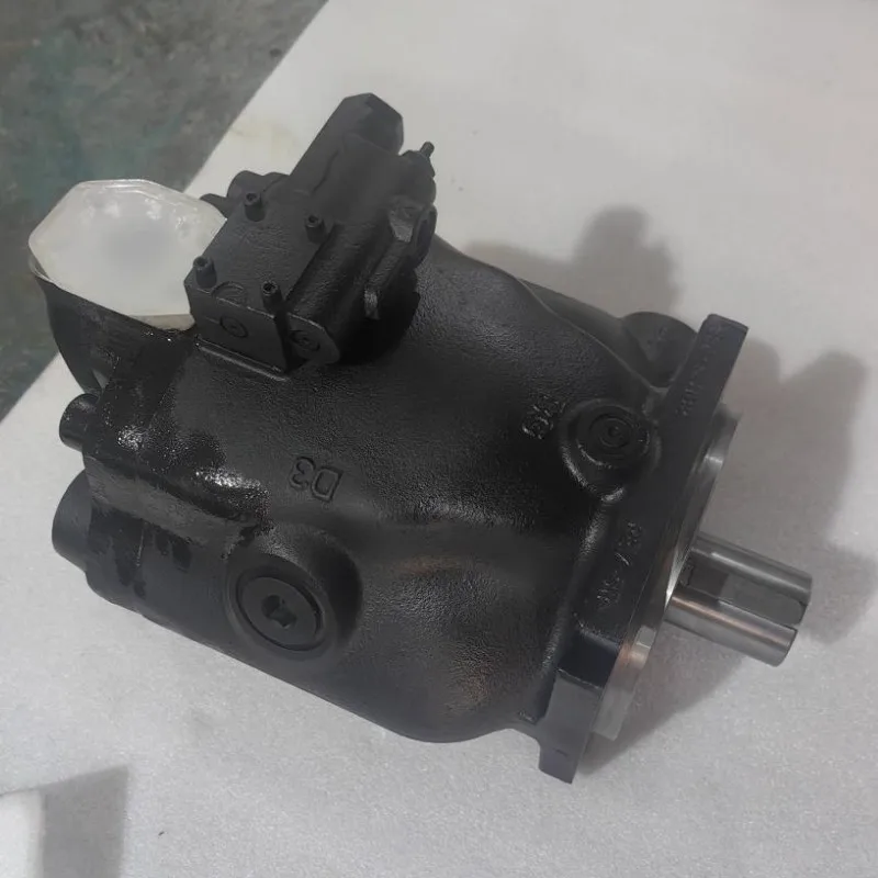
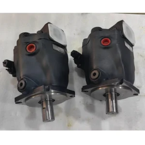
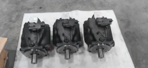

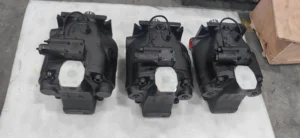
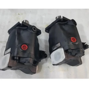

Hydraulic Pump PD045 PD060 PD075 PD100 PD140 PD P1 Series PD140PM04SRS5BL0TS0000000 High Pressure Hydraulic Variable Piston Pump
1.
Core parameters of displacement and pressure: Theoretical displacement: 140 mL/r (milliliters per revolution), which is a large-displacement specification, providing core power for large heavy-duty hydraulic systems
2.
Pressure rating: Continuous rated pressure 28 MPa (280 bar), capable of withstanding high-intensity cyclic operations for a long time. The instantaneous peak pressure is 35 MPa (350 bar), with a single duration of no more than 10 seconds. It is suitable for extreme working conditions such as start-up shock and sudden load changes
3.
Regulation characteristics: Minimum regulation pressure ≤12 bar, pressure compensation regulation accuracy ±2%, supports precise control of low pressure and small flow
4.
Rated speed: 1000-2000 rpm, suitable for the common output speeds of large engines and industrial motors
5.
Flow output: At a rated speed of 2000 rpm, the maximum flow rate can reach 280 L/min, meeting the requirements for the coordinated operation of 3 to 4 large actuating components. The flow stability error at a low speed of 50 rpm is ≤3%
6.
Steering requirements: Unidirectional clockwise rotation. The shaft end adopts involute spline transmission (specification 6×2.5×30), and the transmission torque is 40% higher than that of flat keys
7.
Structure and material Specifications: Structural type: Axial piston variable pump, featuring a symmetrical arrangement of 11 pistons and pre-compression volume compensation technology, with a flow pulsation rate of ≤3%
8.
Core materials: The pump body is made of high-strength forged alloy steel (quenched and tempered, hardness HB280-320), the plunpiston is made of nitrided alloy steel (surface hardness HV1000-1100), and the oil distribution plate is made of copper-based alloy + silicon carbide coating
9.
Control mode: Pressure compensation + mechanical feedback variable control, equipped with an independent unloading valve group, supporting load adaptive regulation
10.
Installation and adaptation parameters Installation specifications: SAE E type flange installation, spline connection at the shaft end, positioning pin diameter Φ12mm, shell sealing adopts fluororubber O-ring (temperature resistance -30℃ to 120℃)
11.
Shell features: Supports high shell pressure operation, continuous shell pressure ≤25 bar, short-term peak shell pressure ≤30 bar, suitable for installation in narrow Spaces
twelve
Weight and dimensions: The overall weight of the machine is 95 kg, with a length × width × height of 580×320×410 mm. The structure is compact and suitable for integration with large-scale equipment
13.
Oil and environmental requirements: Oil specifications: It is recommended to use L-HM 68 anti-wear hydraulic oil. For cold regions (below -30℃), L-HV 68 low-temperature anti-wear hydraulic oil should be selected. The viscosity range of the oil is 25-400 mm²/s
fourteen
Working environment: The oil cleanliness should reach ISO 16/13 grade (NAS 7 grade), the working oil temperature should be -25℃ to 85℃, and the relative humidity should be ≤95% (without condensation).Ii. Working Principle
This pump is an axial piston variable pump. Its core achieves stable output of high-pressure oil through a closed-loop mechanism of “piston reciprocation – volume change – pressure feedback regulation”. Combined with an 11-piston structure and pressure compensation technology, it enhances operational stability. The specific process is as follows:
1.
Power transmission and suction oil circulation: The power source drives the transmission shaft to rotate through involute splines, which in turn rotates the cylinder block synchronously. Under the combined action of centrifugal force and return spring, the ball heads of the 11 plungers are always in close contact with the working surface of the swash plate. Due to the adjustable tilt Angle (0-20°) of the swash plate, when the plunger rotates with the cylinder block, it moves back and forth along the cylinder block holes in a straight line. When moving from the lower position to the higher position of the swash plate, the plunger extends out of the cylinder block, increasing the volume of the sealed cavity to form a vacuum, and the oil is sucked in through the SAE 3-inch oil suction port. When moving from the high position to the low position, the plunger retracted into the cylinder body, the cavity volume was compressed, and the high-pressure oil was output to the hydraulic system through the SAE 2.5-inch oil pressure port.
2.
11 Plunger flow stabilization mechanism The design adopts a symmetrical and uniform arrangement of 11 plungers, combined with the pre-compression volume compensation technology, which reduces the flow fluctuation range during the oil conversion process of adjacent plungers’ suction pressure to less than 3%. Compared with the traditional 6-9 plunger structure, the hydraulic shock is reduced by 50%, the system vibration acceleration is ≤ 0.5g, and the operating noise is reduced to less than 78 dB (under 2000 rpm conditions).
3.
Pressure compensation variable regulation: The built-in pressure compensation valve collects the system outlet pressure in real time. When the pressure reaches the rated value of 28 MPa, the valve core of the compensation valve overcomes the spring force and moves. Through the mechanical feedback mechanism, it pushes the swash plate to reduce the inclination Angle, and the displacement decreases accordingly to maintain pressure stability. When the load drops and the system pressure decreases, the spring returns to push the swash plate to increase its Angle, increasing the displacement to meet the flow demand and achieving the energy-saving effect of “fuel supply on demand”, saving 25% to 30% energy compared with the fixed displacement pump.
4.
High shell pressure adaptation mechanism: The pump body is made of forged alloy steel optimized by FEM, combined with a double lip seal structure, enabling the shell to withstand a continuous pressure of 25 bar. When the installation space is limited and the pressure on the shell increases, the built-in shell pressure relief valve automatically opens to unload, preventing the pump body from cracking or the seal from failing.
Iii. Product Features and Advantages
1.
Outstanding adaptability for large displacement and heavy load: The 140 mL/r large displacement pump can output a flow rate of 280 L/min at 2000 rpm, and can simultaneously supply oil to 3 to 4 large actuating components (such as the excavator boom, bucket arm, and slewing mechanism). It supports the coordinated operation of complex compound actions, and its working efficiency is 16% higher than that of the 120 mL/r pump of the same level. It is suitable for the heavy-load requirements of equipment over 30 tons.
2.
Excellent high-pressure wear resistance and reliability: The surface nitriding treatment (HV1000-1100) of the plunger and the silicon carbide coating on the oil distribution plate form a highly efficient wear-resistant pair. Under a rated pressure of 28 MPa, the trouble-free working life exceeds 12,000 hours. The forged alloy steel pump body has an impact resistance strength of 120 J/cm², which can withstand frequent load fluctuations in harsh environments such as mines.
3.
Low pulsation and low noise design: The symmetrical arrangement of 11 plungers and pre-compression technology ensure that the flow pulsation rate is ≤3%, reducing system hydraulic shock by 50% and extending the service life of peripheral components such as valve groups and pipelines by 30%. The optimized flow channel structure and noise-reducing shell design result in a noise level of only 78 dB at 2000 rpm, which is 5-8 dB superior to products of the same specification in the industry.
4.
Wide operating conditions and high adaptability: It operates within a wide temperature range of -25℃ to 85℃. There is no jamming when starting at low temperatures in cold regions, and the oil temperature remains stable within 80℃ in high-temperature environments. The 25 bar high housing pressure design is suitable for installation in narrow Spaces, and the involute spline transmission is suitable for the high torque output requirements of large power sources.
5.
Energy conservation and convenient maintenance: The pressure compensation variable control reduces the annual energy-saving cost by 25% to 30% compared with the fixed displacement pump. The modular design enables the unloading valve group, seals and other vulnerable parts to be replaced separately, reducing the troubleshooting time to within 40 minutes and increasing maintenance efficiency by 45%.
Iv. Usage Functions and Purposes
1. Core usage functions
•
Heavy-duty power output: 28 MPa rated pressure +280 L/min large flow output, providing stable power for large hydraulic systems, driving the actuator to perform high-intensity actions such as excavation, lifting, pressing, and pushing, and supporting the compound and collaborative operation of multiple actuators.
•
Pressure and flow adaptive control: The pressure compensation variable system achieves “constant pressure energy supply”, automatically adjusting the flow when the load changes. The pressure fluctuation error is ≤2%, making it suitable for precise pressure control scenarios such as mold locking in injection molding machines and pressing in presses.
•
Overload and safety protection: Built-in pressure relief valve and shell pressure unloading valve. When the system pressure reaches a peak of 35 MPa or the shell pressure exceeds 25 bar, it will automatically unload to prevent damage to the pump body and system components. The response time of the mechanical feedback mechanism is ≤60 ms, and the overload protection is more rapid.
2. Main application fields
•
Large-scale construction machinery: main hydraulic systems for 30-50 ton crawler excavators, oil supply for lifting/tipping buckets of 20-30 ton wheel loaders, luffing/telescopic/lifting systems for 15-25 ton all-terrain cranes, drive systems for large mining loaders.
•
Industrial and metallurgical equipment: 2000-4000 ton hydraulic press pressing power source, large-scale steel rolling mill roll adjustment and pressing system, heavy forging equipment hydraulic drive, port container crane lifting/translation oil supply.
•
Mining and special machinery: Drive systems for large underground mine loaders (over 10 tons), power sources for open-pit mining hydraulic drilling RIGS, propulsion and segment assembly systems for large shield machines, and lifting drives for heavy-duty fire truck ladders.
V. Applicable Machines and Scenarios
1. Adapt to the core machine
•
Construction machinery: 30-50 ton excavators, 20-30 ton loaders, 15-25 ton cranes, large mining loaders.
•
Industrial equipment: 2000-4000 ton hydraulic presses, large-scale steel rolling mills, heavy forging equipment, port container cranes.
•
Special machinery: 10-ton and above mining loaders, large mining drilling RIGS, shield machines, heavy-duty fire engines.
2. Typical application scenarios
•
Large-scale heavy-load composite scenarios: 30-ton class excavators perform combined actions of digging, slewing and walking, and cranes work in coordination with luffing, extension and lifting. With a pressure of 28 MPa and a flow rate of 280 L/min, multiple actuating components can supply oil simultaneously, and the operation efficiency is 30% higher than that of small-displacement pumps of the same level.
•
Harsh mining environment scenarios: Underground mine dust environment, open-pit mine rock excavation conditions. High-strength pump body and anti-pollution structure design (compatible with ISO 16/13 grade oil), maintenance cycle extended to over 2000 hours, equipment downtime loss reduced by 65%.
•
Precision heavy-load control scenarios: Precise pressing of large presses, fine-tuning of roll clearance in steel rolling mills, pressure regulation accuracy ±2%, keeping the dimensional tolerance of workpieces within 0.05mm, and increasing the product qualification rate by 10%.
•
Continuous high-intensity scenarios: Metallurgical workshop steel rolling systems, port cranes operate continuously for 24 hours. With high wear-resistant materials and stable heat dissipation design, the monthly failure rate is less than 0.3%, and the annual continuous operation time exceeds 7,000 hours.
Six. Similar models
1. Alternative models of the same series
•
PD120PM04SRS5BL0TS0000000: series with PD140 model, control method (pressure compensation + mechanical feedback), theory of displacement to 120 mL/r, 28 MPa pressure rated, adapter excavator, 25 to 30 ton compatible with PD140 installation size.
•
With PD140PM04 PD140PE04SRS5BL0TS0000000: displacement and pressure parameters, the control method to upgrade for the electro-hydraulic proportional control, support 0 to 10 v / 4-20 ma remote adjustment, adaptive automatic production line, intelligent engineering machinery, etc.
2. Cross-series alternative models
•
A4VG140HD3/32R-NZD02F001S: Axial piston variable pump, displacement 140 mL/r, rated pressure 31.5 MPa, mechanical hydraulic control, suitable for extreme heavy-load scenarios in mines, with a 20% higher impact resistance than the PD series.
•
HPV140-280: Axial piston pump, displacement 140 mL/r, rated pressure 28 MPa, dual oil distribution plate structure, volumetric efficiency ≥95%, weight 10% lighter than PD series, suitable for large equipment with limited installation space.
•
SV140-35: A large-displacement plunger pump with a displacement of 140 mL/r, a rated pressure of 35 MPa, and a peak pressure of 40 MPa. It is suitable for ultra-high pressure and heavy-load scenarios (such as large forging equipment), and its service life is 25% longer than that of the PD series.
Vii. Precautions for Use
1.
The core norms for oil management strictly select L-HM 68 or L-HV 68 anti-wear hydraulic oil. It is prohibited to mix oils of different brands and grades to avoid abnormal wear of the plunger and the oil distribution plate. The first oil change cycle is 1000 hours, and then it should be changed every 2,500 to 3,000 hours. Before changing the oil, the pump chamber and pipelines should be flushed with new oil (the flushing oil volume should be no less than twice the system volume).
2.
A 10μm high-pressure filter must be installed at the oil inlet, and a 20μm fine filter at the oil return port. The contamination level of the filter should be checked every 800 hours. When the pressure difference exceeds 0.35 bar, the filter element should be replaced immediately. The fuel tank needs to be cleaned every 6,000 hours. The sediment thickness should be no more than 1mm and the moisture content of the oil should be no more than 0.1%.
3.
The installation and commissioning requirements require the use of elastic couplings for connection. The coaxiality error of the two shafts should be ≤ 0.1mm, and the angular error should be ≤0.3°. This is to prevent radial force from causing the transmission shaft to bend and the cylinder block to wear off-center (reducing service life by more than 60%). When installing the SAE E type flange, the bolts should be evenly tightened with a pre-tightening torque of 80-100 N·m to prevent high-pressure leakage.
4.
The diameter of the oil suction pipeline is ≥Φ100mm, the length is ≤3m, the number of elbows is ≤2, and the oil suction resistance is ≤ 0.015MPa (to prevent cavitation). The oil pressure pipeline should be equipped with a 0-40 MPa high-pressure pressure gauge and pressure sensor to monitor the system pressure in real time. The spacing of pipeline supports should be no more than 1.5 meters to reduce vibration.
5.
Before the initial start-up, clean hydraulic oil should be filled into the pump body. Manually turn the pump 10 to 15 times to ensure there is no jamming. When starting at a temperature below -20℃, heat the oil to above -10℃ and run it at a low speed of 800 rpm without load for 15 minutes. When the oil temperature rises above 35℃, gradually increase the load (pressure increase rate ≤3 MPa/ minute). It is strictly prohibited to run the machine at full load when it is cold.
6.
Core parameters that need to be monitored during operation: oil temperature 35-80℃ (if it exceeds 85℃, the machine should be shut down to check the cooling system), system pressure ≤28 MPa (peak value not exceeding 35 MPa and single time ≤10 seconds), shaft end leakage ≤5 drops per minute, vibration acceleration ≤ 0.5g. If abnormal sounds occur, pressure drops sharply, oil temperature exceeds 90℃ or leakage exceeds the standard, the machine must be stopped immediately for inspection.
7.
Maintenance and servicing nodes should inspect the condition of the shaft seal and fluororubber sealing parts every 1500 hours. Replace them immediately if aging, cracking or excessive leakage occurs. Disassemble and inspect every 8,000 hours. If the surface scratch of the plunger is greater than 0.03mm, the flatness error of the oil distribution plate is greater than 0.015mm, or the wear of the cylinder block hole exceeds 0.02mm, the corresponding parts need to be replaced.
8.
Calibrate the pressure compensation valve and mechanical feedback mechanism every 2000 hours, and adjust the spring preload through a dedicated test bench to ensure a pressure regulation accuracy of ±2%. Clean the oil passage of the variable mechanism every 4,000 hours to prevent impurities from getting stuck and causing adjustment failure.
9.
Safety and storage requirements: Before maintenance, the power source must be cut off, the system unloading valve opened to release pressure to 0 MPa, and disassembly can only be carried out when the oil temperature drops below 40℃. When disassembling, it is necessary to make proper alignment marks on the cylinder block, distribution plate and swash plate to avoid abnormal wear caused by poor meshing after reassembly.
10.
When the pump is out of service for a long time (more than 6 months), the oil in the pump should be drained and anti-rust oil should be injected (the injection volume should be 80% of the pump body volume). The oil inlet and return ports and the shaft end should be sealed with plastic plugs. The pump should be stored in a dry and well-ventilated environment (humidity ≤60%, temperature 0-40℃). Every 2 months, the pump should be manually turned by hand for 5 turns to prevent rust.
P2145R00D1D25LA20N00D3B1P
P3145R00D1D25LA20N00D3A1P
P2060R00C5C25RA20N00T1A1P
P2060L00C5C25RA20N00T1A1P
P2075R00C6C25RA20N00T1A1P
P2075L00C6C25RA20N00T1A1P
P2060R00C5C25LB20N00T1A1P
P2075R00C6C25LB20N00T1A1P
P2075L00C6C25LB20N00T1A1P
P2145L00D3D25LB20N00T1A1P
P2145R00D3D25LB20N00T1A1P
P2105R00C6C25RA20N00T1A1P
P2105L00C6C25RA20N00T1A1P
P2145R00D3D25RA20N00T1A1P
P2145L00D3D25RA20N00T1A1P
P2105R00C6C25LB20N00T1A1P
P2105L00C6C25LB20N00T1A1P
P2105R00C2C25LA20N00C3A2U
P2105R00C1C25LA20N00B1A4U
P2105L00C2C25LA20N00S1A1U
P3105R00C1C25LA20N00T1A1P
P2105R00C1C25LB20N00T1A1P
P2075R00C6C25TC20N58A1A1P
P2060R00C1C25PA00N00B1A1P
P3145L00D1D25LA20N00T1A1P


