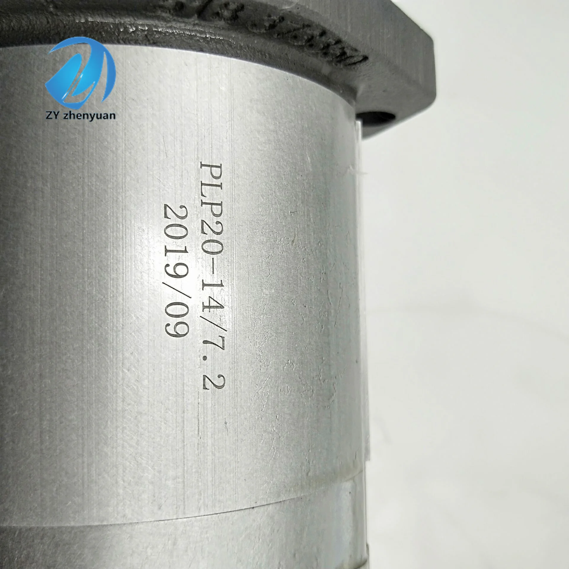


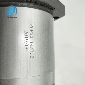

Hydraulic Pump PLP20.8-LGE/GD/20.8-LGD-S7 D/FS EL High Pressure Gear Oil Pump PLP PLP10 PLP20 PLP30 Series Gear Pump
1. Basic performance parameters
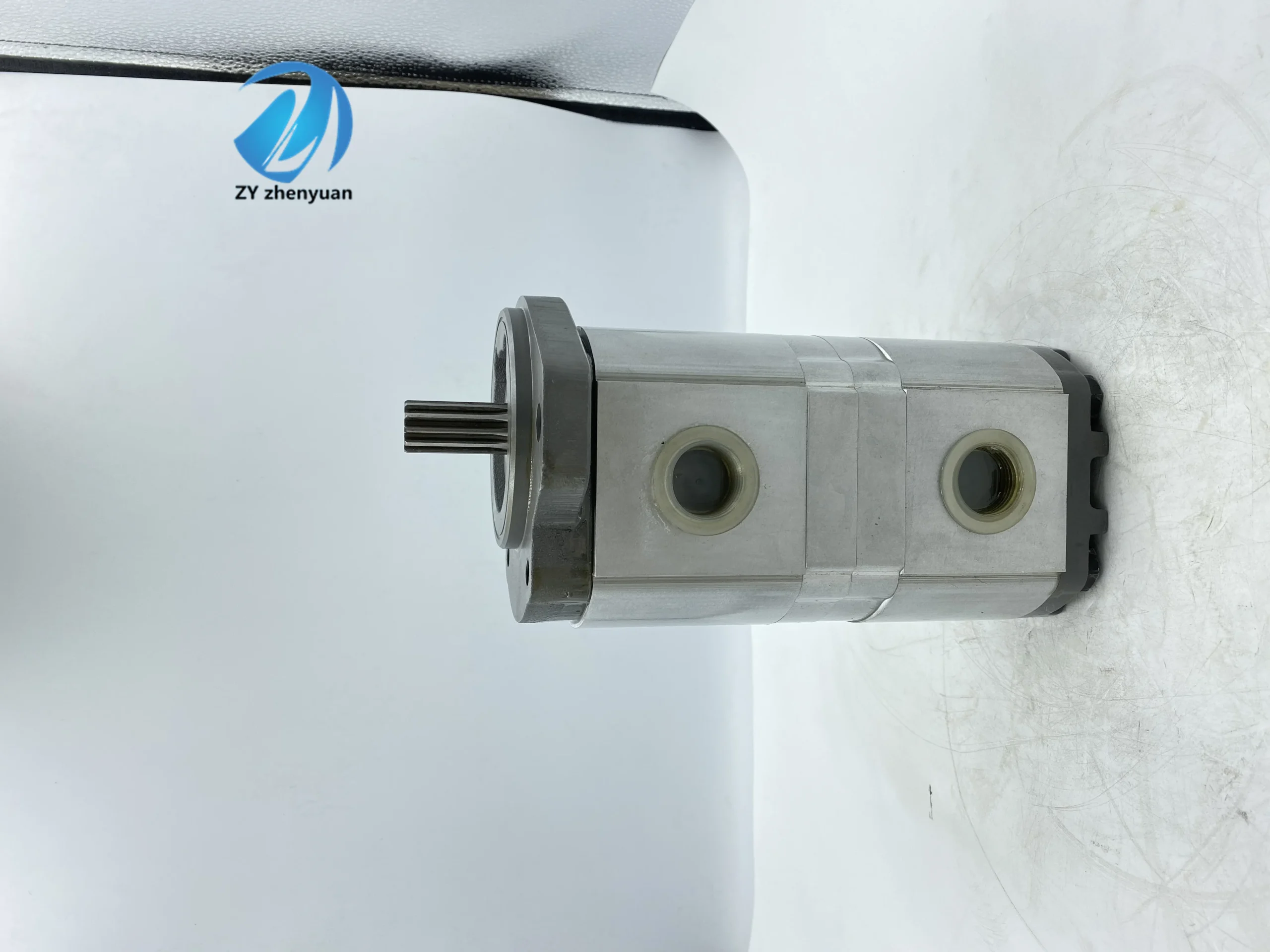
– Pump body type: Double external meshing fixed displacement gear pump, double pump core coaxial drive structure, integrated one-piece relief valve and pressure compensation distribution plate, supporting independent or combined oil supply in dual circuits- Displacement and pressure parameters: Rated displacement of single pump core 20.8cc /rev, total displacement 41.6cc /rev; The rated working pressure is 210 bar, the maximum allowable pressure is 250 bar (short-term ≤10 seconds), and the return oil back pressure is ≤2 bar
– Speed and flow parameters: Rated speed 2800 rpm, maximum speed 4000 rpm (short time ≤5 minutes), minimum stable speed 600 rpm; The total output flow at the rated speed is approximately 116.5 L/min (20.8×2×2800÷1000).
– Efficiency parameters: The volumetric efficiency of a single pump core under rated working conditions is ≥93%, and the total efficiency is ≥88%. The pressure loss at the rated flow is no more than 5 bar, and the dual-loop diversion error is no more than 3%
2. Structure and connection parameters
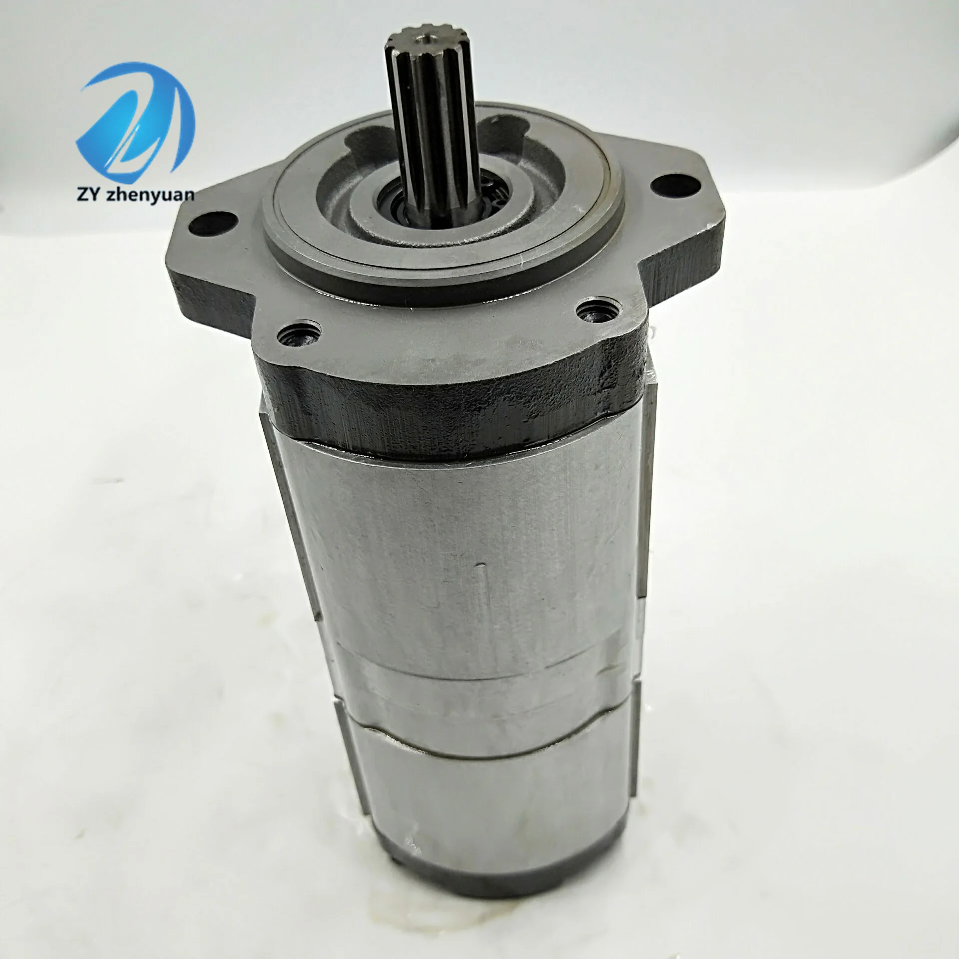
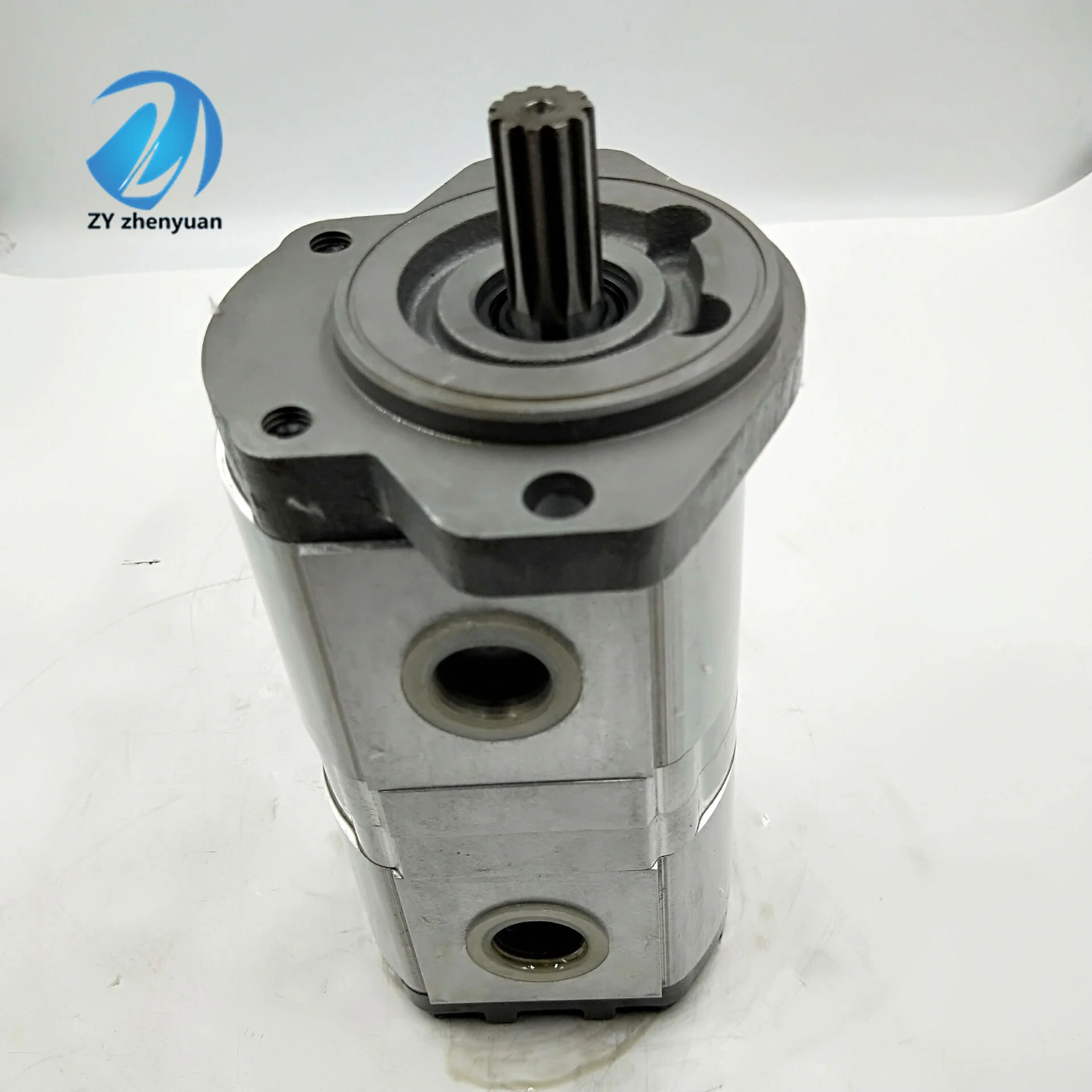
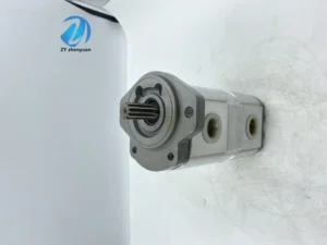
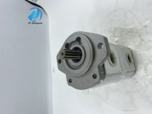
– Structural type: Cast iron integral pump body, nitrided alloy steel gears (hardness HRC62-65), pressure self-compensating distribution plate, double-end mechanical seal; The two pump cores are arranged in parallel, sharing the input shaft, and the integrated oil passage enables internal oil return
– Installation and connection specifications: Flange installation (compatible with ISO 3019-1 standard, model “LGD” corresponds to NG06 installation dimensions); Oil port threads: Suction port (1 in total) G1, dual oil outlet ports G3/4 each, control oil port G1/8; The input shaft is connected by a flat key (specification: 14×35). The overall weight is approximately 18 kg, and the external dimensions (length × width × height) ≈320×210×190 mm
– Core material: The pump body is made of gray cast iron HT250, the gears are chromium-molybdenum alloy steel, the distribution plate is tin bronze, and the sealing parts are a high-pressure resistant fluororubber combination (temperature resistance ≤110℃)
3. Medium and Environmental requirements
– Medium requirements: Compatible with L-HM 32/46/68 anti-wear hydraulic oil, allowable medium viscosity 10-400 mm²/s, moisture content ≤0.02%, solid particle size ≤10 μm
– Environmental parameters: The cleanliness of the oil should reach ISO 4406 14/11 grade; The operating environment temperature ranges from -25℃ to 90℃, with a relative humidity of no more than 95%. The protection grade is IP65, making it suitable for dusty and humid industrial scenarios
Ii. Working Principle
This pump is a double external meshing quantitative gear pump. Its core converts mechanical energy into hydraulic energy through the mechanism of “double gear meshing volume change + double circuit coordination”, achieving stable oil supply in both circuits. The specific process is as follows:
1. Power conversion and fuel supply mechanism
The motor drives the input shaft to rotate the driving gears of the two pump cores synchronously. Within each pump core, the driving gears drive the driven gears to mesh in opposite directions. A local vacuum is formed on the side where the gears disengage, and the hydraulic oil is drawn in through the common suction port to fill the tooth grooves of the gears in the two pump cores respectively. When the gears rotate to the meshing side, the volume of the tooth grooves decreases, squeezing the oil to form pressure. The oil is discharged to the system through their respective independent oil outlets, achieving dual-loop independent oil supply. When a large flow rate is required, the two oil outlets can be combined through external pipelines to achieve a total displacement oil supply.
2. Pressure regulation and protection mechanism
The integrated one-piece relief valve is connected in parallel to the double oil outlet summary oil passage. When the system pressure rises to the rated value of 210 bar, the relief valve begins to unload. When the pressure exceeds the maximum allowable value of 250 bar, the relief valve is fully open to guide the excess oil back to the suction chamber, preventing the pump body and pipelines from being overloaded. The pressure self-compensating distribution plate automatically adheres to the gear end face under the action of pressure oil, compensates for wear clearance, and maintains high volumetric efficiency.
Iii. Product Features and Advantages
– Dual-loop high-efficiency coordination: Dual pump cores are driven on the same axis to achieve 1:1 flow synchronous output. The dual-loop diversion error is ≤3%, which is suitable for the synchronous action requirements of multiple actuating elements. Supports independent or combined fuel supply switching, and the flexibility of flow regulation is 50% higher than that of a single pump
– Compact integrated design: The dual pump cores share the pump body and input shaft, reducing the volume by 40% and the weight by 35% compared to two independent single pumps. Integrate the relief valve with the internal return oil passage to reduce the number of external components and lower the risk of system leakage
– High wear resistance and long service life: Nitrided gears combined with tin bronze distribution plates have excellent wear resistance. The cast iron pump body has strong impact resistance, and the mechanical seal has an outstanding anti-leakage effect. The rated working condition fault-free operation life is ≥ 12,000 hours
– Low noise and stable operation: Optimized tooth profile curve (corrected involute) and high-precision gear meshing clearance (≤ 0.03mm), operating noise ≤ 78dB (measured at 1 meter), 5-8dB lower than conventional double-pump. The flow fluctuation within a wide speed range (600-4000 rpm) is no more than 2%
– Wide working condition adaptability: With a wide temperature range of -25℃ to 90℃ and a high pressure tolerance of 250 bar, it can adapt to harsh working conditions such as high and low temperatures and heavy load fluctuations. Compatible with both flange and foot mounting methods, the oil port position can be adjusted as needed
Iv. Usage Functions and Purposes
1. Core usage functions
– Dual-loop quantitative oil supply: It provides two stable flow and pressure hydraulic oil channels for the hydraulic system, driving two independent actuating elements (such as cylinders and motors) to act synchronously or sequentially
– Flow rate switching as needed: When the dual oil outlets are independently supplied with oil, the single-channel flow rate is 58.2L /min, and when they are combined for oil supply, the total flow rate is 116.5L /min, adapting to the flow rate requirements of different loads
– System pressure protection: The built-in relief valve precisely controls the maximum pressure of the system to prevent overload damage. The pressure self-compensation mechanism maintains the long-term stability of volumetric efficiency
– Efficient medium transmission: It conveys hydraulic oil free of solid particles and with lubricity, achieving efficient conversion between mechanical energy and hydraulic energy, and transmitting power to the terminal actuator
2. Main uses
As a core power component of multi-actuator hydraulic systems, it is suitable for scenarios that require dual-loop synchronous or independent oil supply, connecting the power source (motor) with the actuator, providing precise power distribution for various types of machinery, and is a key component of complex hydraulic transmission systems.
V. Applicable Machines and Scenarios
1. Adapt to the core machine
– Construction machinery: 5-10 ton excavators, 3-5 ton loaders, telescopic boom forklifts, rollers
– Industrial machinery: 200-500 ton injection molding machines, 100-300 ton presses, CNC lathes (double stations), fully automatic packaging machines
– Agriculture and special machinery: Large combine harvesters, corn harvesters, aerial work platforms, ship deck winch systems
2. Typical application scenarios
– Dual-action scenario for excavators: As the hydraulic power source for 8-ton excavators, it uses dual circuits to drive the boom cylinder and the bucket rod cylinder respectively. When the rated pressure is 210 bar and the single-circuit flow rate is 58.2 L/min, it can achieve synchronous boom lifting and lowering and bucket rod retraction and extension actions. The response time for compound actions is ≤0.3 seconds, and it is equipped with IP65 protection, making it suitable for dusty construction sites
– Injection molding machine molding scenario: It is equipped with a 300-ton injection molding machine. The dual circuits respectively control the clamping cylinder and the injection cylinder. When the oil supply is combined, the total flow rate is 116.5L /min to achieve rapid clamping. When the oil supply is independent, the injection pressure and speed are precisely controlled. The volumetric efficiency is 93% to ensure the molding accuracy is ≤± 0.1mm
– Combine harvester operation scenarios: Drive the header lifting and conveyor chain drive of large combine harvesters, dual-loop flow output synchronously, header lifting speed 0.8m /s, conveyor chain speed 150 r/min, wide temperature range suitable for field operation environment from -5℃ to 40℃
Six. Similar models
1. Different models of the same series displacement
-PLP16.0-LGE /GD/16.0-LGD-S7 D/FS EL: The rated displacement of the single pump core is 16.0cc /rev, the total displacement is 32.0cc /rev, and the rated flow rate is 89.6L /min. It is suitable for small dual-loop systems (such as loaders under 5 tons and small CNC lathes), with a more compact volume and a 20% lower cost
-PLP25.0-LGE /GD/25.0-LGD-S7 D/FS EL: The rated displacement of the single pump core is 25.0cc /rev, the total displacement is 50.0cc /rev, the rated flow rate is 140 L/min, and the maximum pressure is 250 bar. It is suitable for large equipment (such as 10-ton excavators, 500-ton presses), and has stronger power
2. Models with the same displacement but different functions
-PLP20.8-LGE /GD/ 20.8-LGD-S7M /FS EL: Manually adjustable relief valve model, suitable for simple dual-loop systems with fixed pressure, featuring a more concise structure and a 15% lower cost
-PLP20.8-LGE /GD/ 20.8-LGD-S7E /FS EL: Electro-hydraulic proportional control model, supporting remote adjustment of dual-loop pressure and flow, control accuracy ±2%, suitable for automated production lines, with a 40% higher cost
-PLP20.8-LGE /GD/ 20.8-LGD-S7D /FT EL: Foot-mounted model, suitable for equipment without flange installation space. Other performance is the same as the original model, and the installation flexibility is higher
PLP20.11,2-03S1-LOC/OC/20.9-LOC/OC D FS
PLP20.11,2-31S1-LOC/OC/20.11,2-LOC/OC D/FS-EL
PLP20.11,2-31S1-LOC/OC/20.6,3-LOC/OC D/FS-EL
PLP20.16-03B5-LBE/BC/20.14-LBE/BC S/FS EL
PLP20.16-03B5-LBE/BC/20.4-LBE/BC S/FS EL
PLP20.8-96R2-LBE/BC/20.4-LBE/BC D/L FS
PLP20.16-12B2-LBE/BC/20.11,2-LBE/BC D/FS EL AV
PLP20.6,3/20.4 D FS
PLP20.8/20.8 D FS
PLP20.8/20.4 D FS
PLP20.11,2/20.11,2 D FS
PLP20.16/20.8 D FS
PLP20.20/20.14 S FS
PLP20.20/20.8 D FS
PLP20.20/20.6,3 D FS
PLP20.25/20.14 D FS
PLP20.25/20.8 D FS
PLP20.25/20.6,3 D FS
PLP20.31,5/20.16 D/FS-E
PLP20.31,5/20.16 D/FS
PLP20.8-LGD/GD/20.8-LGD/GD D FS EL AV
PLP20.11,2-LGD/GD/20.11,2-LGD/GD D FS EL
PLP20.11,2-LGD/GD/20.8-LGD/GD D FS EL
PLP20.11,2-LGD/GD/20.8-LGD/GD S/ FS EL
PLP20.11,2-LGD/GD/20.6,3-LGD/GD D FS EL
PLP20.11,2-LGD/GD/20.4-LGD/GD D FS EL
PLP20.14-LGE/GD/20.11,2-LGD/GD D FS EL
Vii. Precautions for Use
Installation and commissioning
When installing, ensure that the coaxiality error between the input shaft and the motor shaft is ≤ 0.1mm. Use an elastic coupling for connection. It is strictly prohibited to directly apply radial or axial force to the pump shaft to avoid abnormal gear meshing
The oil suction pipeline should be short and thick (length ≤2 meters, diameter ≥ 32mm), the distance between the oil suction port and the bottom of the oil tank should be ≥ 100mm, and the filtration accuracy of the filter should be ≥80 mesh. The pipeline connection must be tightly sealed to prevent air leakage, which may lead to insufficient oil absorption and cause cavitation
Before the first start-up, hydraulic oil should be injected into the pump cavity, and the pump should be manually turned by hand for 3 to 5 turns to ensure there is no jamming. When starting up, first open the oil suction valve and run it no-load at low pressure (50 bar) and low speed (1000 rpm) for 30 minutes. Gradually increase it to the rated parameters and check the consistency of the dual-circuit flow at the same time
For outdoor installation, a protective cover should be added to avoid direct sunlight and rain. Reserve a heat dissipation space of ≥ 200mm around the pump body, keep it away from high-temperature heat sources (such as engine exhaust pipes), and force heat dissipation when the ambient temperature exceeds 40℃
2. Operation and Maintenance
During operation, monitor the pump body temperature (normal ≤85℃, maximum ≤95℃), pressure fluctuations in the dual circuits and noise every week. If the temperature rises sharply by more than 15℃, the pressure fluctuates by more than 5 bar or the noise exceeds 85 dB, stop the machine immediately for inspection. Focus on checking the oil contamination level (once every three months), gear wear or seal leakage
– Regular maintenance cycle: Replace the hydraulic oil and suction and return oil filters every 5,000 hours. Disassemble and inspect the gear wear every 10,000 hours (replace when the tooth surface wear is ≥ 0.1mm), and replace the mechanical seal and bearing. The pressure setting value of the relief valve should be calibrated every 2000 hours
It is strictly prohibited to run the machine without oil (idling for more than 5 seconds can easily cause damage to gears and bearings). Do not operate for a long time at the maximum speed (no more than 15 minutes at a time). When the system is overloaded, it should be shut down in time to prevent the relief valve from being unloaded for a long time, which may cause the oil temperature to be too high
3. Storage and Protection
When stored for a long time, all oil ports should be sealed with special plugs. Anti-rust oil should be injected into the pump cavity, and lithium-based grease should be applied to the keyway of the input shaft. Store in a dry warehouse with a temperature ranging from 0 to 45℃ and a humidity of no more than 60%. Avoid direct sunlight and heavy object compression. Manually turn the machine once every three months
Before putting the pump back into use after being idle for more than 12 months, thoroughly clean the pump cavity and pipelines, replace all seals and hydraulic oil, and recalibrate the pressure of the relief valve. Run the low-speed no-load test for 20 minutes to check the consistency of the flow rate and leakage of the dual circuits (a single circuit leakage of ≤2 mL/min is normal). Only after meeting the standards can it be connected to the system


