

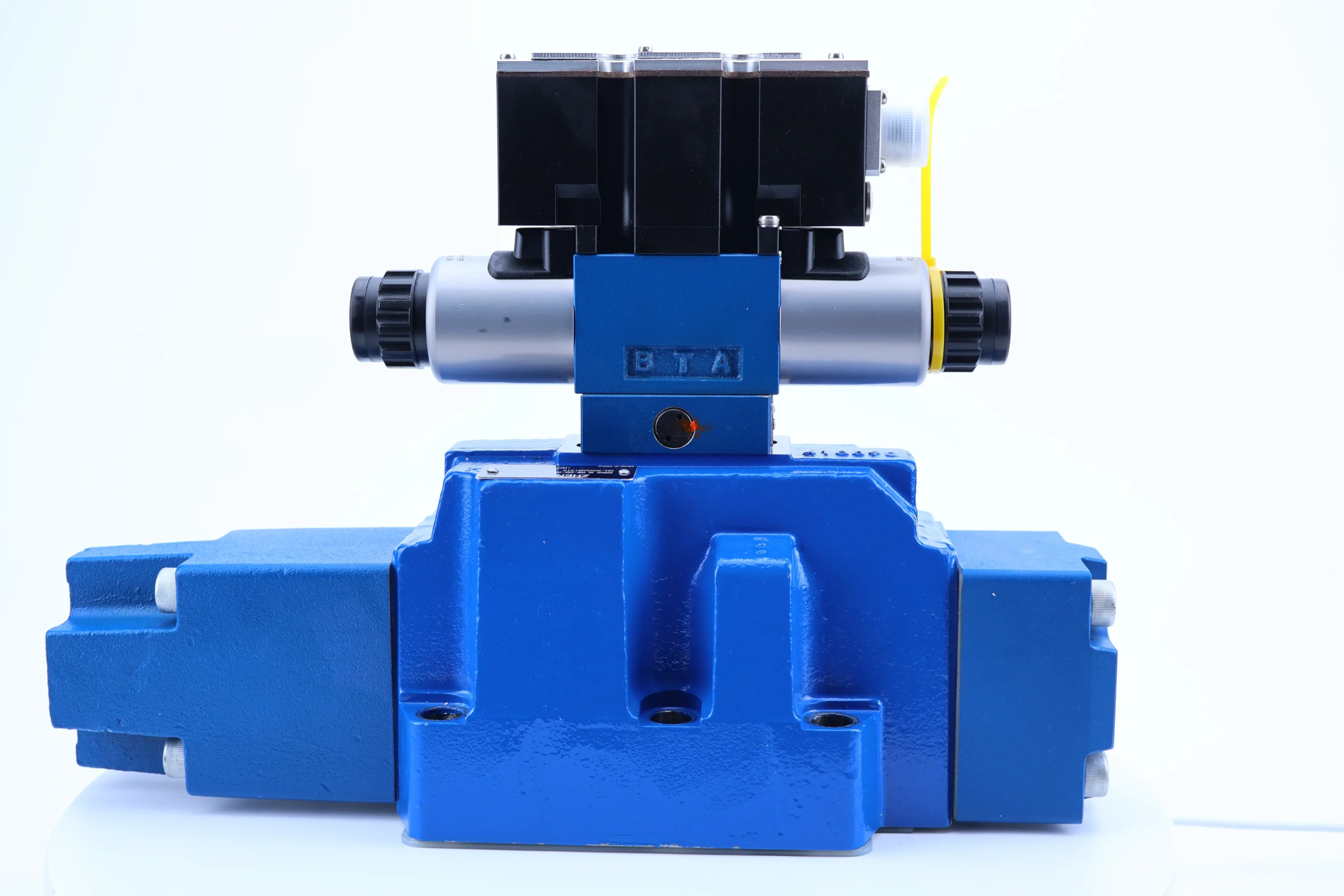
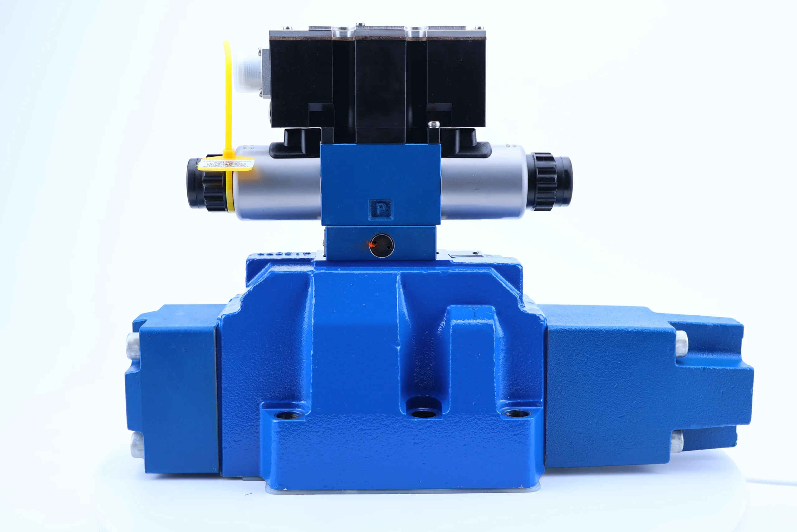


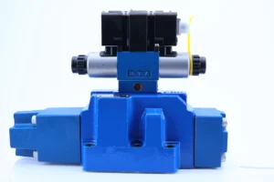
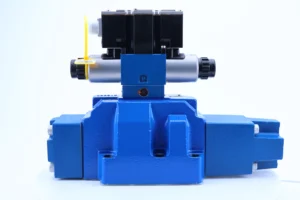
Proportional Hydraulic Valve 4WRZ 4WRZE10 25 32 4WRK 4WRKE Series 4WRZE25W6-220-7X/6EG24NJETK31 Solenoid Control Valve
1. Diameter and pressure rating
Nominal diameter: 25mm, suitable for medium and high-pressure high-flow hydraulic systems.
Pressure range: Continuous working pressure 220 bar, instantaneous peak pressure 315 bar (single duration ≤10 seconds), capable of withstanding heavy load impact.
Flow characteristics: Rated flow rate of 300-500 L/min at Δp=10 bar (depending on the valve core design), suitable for the coordinated operation of multiple actuators.
2. Control and electrical parameters
◦ Input signal: Analog signal (0-10V DC or 4-20mA), supporting proportional electromagnet drive, response time ≤ 10ms (10%-90% step signal).
◦ Supply voltage: 24V DC (fluctuation range ±10%), power consumption ≤30W, with reverse polarity protection and short-circuit protection.
◦ Electronic interface: DIN EN 175201-804 standard plug, supporting PWM modulation and fault diagnosis functions.
3. Structure and Materials
◦ Valve core type: Spool valve structure, with ceramic coating (surface hardness HV1200-1400), wear-resistant life exceeds 10,000 hours.
Valve body material: High-strength aluminum alloy (tensile strength ≥350 MPa after heat treatment), oil distribution plate is copper-based alloy + diamond coating.
Sealing form: fluororubber + polytetrafluoroethylene combined seal, temperature resistance range -25 ℃ to + 110℃.
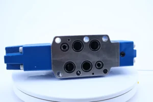
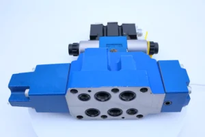
4. Installation and Adaptation
Installation method: ISO 4401-03-02-0-05 standard plate installation, positioning pin diameter Φ 12mm, and the installation torque is uniformly controlled at 80-120 N · m.
◦ Oil port specifications: P (inlet oil port), A/B (working oil port) are G2 1/2, T (return oil port) is G3, and control oil port is G1/4.
Weight and dimensions: approximately 28 kg, external dimensions 320×220×180 mm, compact design suitable for space-constrained scenarios.
5. Oil and environmental requirements
◦ Oil type: L-HM 46 anti-wear hydraulic oil (L-HV 46 low-temperature oil is selected below -25℃), viscosity range: 15-400 mm²/s.
◦ Cleanliness standard: ISO 4406 18/15 grade (NAS 7 grade). It is recommended to install a 10μm filter element at the oil inlet and a 5μm filter element at the oil return port.
◦ Working environment: Humidity ≤95% (no condensation), vibration ≤5g (10-2000 Hz), capable of adapting to harsh working conditions such as dust and oil stains.Ii. Working Principle
This valve is a pilot-operated proportional directional valve. It achieves precise flow and direction regulation through closed-loop control. The core mechanism is as follows:
The pilot control mechanism inputs electrical signals to drive the proportional electromagnet to generate thrust, which pushes the pilot valve core to move and forms a pilot pressure difference. The pilot pressure is applied to both ends of the main valve core through the servo oil circuit, overcoming the spring force to cause the main valve core to move proportionally (displacement accuracy ≤± 0.02mm).
2. The opening degree of the main valve core for flow ratio regulation has a linear relationship with the input signal (linearity error ≤±1.5%). By changing the connection area of the P-A/B-T oil port, the flow can be adjusted steplessly from 0 to 100%. For instance, when a 5V signal is input, the valve core opening is 50%, and the flow output is 50% of the rated value.
3. Pressure compensation function: The built-in pressure compensator automatically balances load changes to ensure that the flow rate is solely determined by the input signal. When the load pressure fluctuates by ±20 bar, the flow stability error is ≤±2.5%, making it suitable for variable load scenarios such as presses and injection molding machines.
4. Dynamic response optimization adopts a lightweight valve core (mass ≤ 0.8kg) and an optimized flow channel design, combined with PWM modulation technology. The step response time is ≤ 10ms, and the overshoot is ≤5%, meeting the requirements of high-speed dynamic control (such as hydraulic servo systems).
Iii. Product Features and Advantages
1. High-precision control capability
A hydraulic positioning system with control accuracy of ±1.5% (linearity) and hysteresis ≤1%, suitable for precision processing equipment (such as five-axis linkage machining centers).
It has a strong ability to suppress pressure fluctuations. Under a working pressure of 220 bar, the pressure pulsation is ≤±2 bar, reducing system vibration and noise.
2. Wide adaptability to working conditions
It supports wide temperature range operation from -25 ℃ to + 110℃, with no jamming when starting in cold regions and stable performance in high-temperature environments.
Its anti-pollution capacity is superior to the industry standard (ISO 18/15 grade), and it can adapt to dusty scenarios such as mining machinery and agricultural machinery.
3. Energy conservation and reliability
Proportional regulation reduces throttling losses, saving 15% to 20% energy compared to traditional directional control valves, and lowering annual operating costs by over 50,000 yuan (calculated based on 24-hour continuous operation).
The ceramic-coated valve core and wear-resistant sealing design ensure a trouble-free operation life of over 15,000 hours and extend the maintenance cycle by 50%.
4. Standardization and scalability
It complies with the ISO 4401 standard installation interface and can directly replace similar products (such as A series, PVH series), reducing the difficulty of transformation.
It supports multiple control modes (pressure control, flow control, position control), and can be adapted to different working conditions through software parameter adjustment.
Iv. Usage Functions and Purposes
1. Core usage functions
Flow and direction control: By continuously regulating the flow and direction of the oil through analog signals, precise control of the speed and position of the actuator is achieved.
Pressure compensation and overload protection: The built-in pressure compensator automatically balances the load, and in combination with the system relief valve (recommended setting pressure of 240 bar), overload protection is achieved.
◦ Fault diagnosis and feedback: The electronic module monitors the valve core position and current consumption in real time, and outputs fault codes through LED indicator lights or bus communication.
2. Main application fields
◦ Construction machinery: Multi-way valve control for 20-30 ton excavators, steering systems for loaders, and impact frequency regulation for hydraulic breakers.
◦ Industrial equipment: Control of blank holder force for 1000-2000 ton hydraulic presses, adjustment of injection speed for injection molding machines, and synchronous drive for metal forming machines.
Specialized machinery: Hydraulic servo systems for ship steering gears, swing control of cutting heads for mine boring machines, and high-precision positioning for medical imaging equipment.
V. Applicable Machines and Scenarios
1. Adapt to the core machine
◦ Construction machinery: hydraulic excavators, loaders, rollers, pavers.
◦ Industrial equipment: hydraulic presses, injection molding machines, die-casting machines, automated production lines.
Specialized machinery: ship deck machinery, mining machinery, precision test benches.
2. Typical application scenarios
◦ Multi-actuator coordinated control: Injection molding machine clamping (high pressure and low flow) – injection (medium pressure and high flow) – pressure holding (low pressure and low flow) cycle, smooth action switching is achieved through proportional valves.
High-speed dynamic response scenario: The metal forming machine tool slider rapidly descends (500 mm/s) – slowly presses (5 mm/s) – quickly returns, with a response time of ≤10 ms to ensure processing accuracy.
◦ Harsh operating conditions: Open-pit mine excavators can still maintain stable operation under the working conditions of -20 ℃ low temperature and dust concentration > 100 mg/m³.
Six. Similar models
1. Alternative models of the same series
◦ 4WRZE25W8-325-7X: The pressure rating has been upgraded to 325 bar, making it suitable for ultra-high pressure systems (such as deep-sea exploration equipment), and the installation dimensions are compatible with the 220 bar model.
◦ 4WRZE25E-220-7X: Valve core with displacement sensor (LVDT), supporting closed-loop position control, control accuracy up to ± 0.01mm, suitable for precision machine tools.
2. Cross-series alternative models
A10VSO140DR/31R-PPB12N00: Axial piston variable pump with proportional valve, flow range 140 L/min, pressure rating 315 bar, suitable for heavy-duty scenarios in construction machinery.
PVH74-QIC-RAF-1S-10-C25-31: Pressure-compensated proportional valve with stronger anti-pollution ability (ISO 19/16 grade), suitable for agricultural machinery and mining machinery.
HPV63-21: An economical proportional valve, with a cost 20% lower than that of the 4WRZE series, is suitable for general industrial equipment with low precision requirements.
Vii. Precautions for Use
1. Oil and fluid management norms
Select L-HM 46 hydraulic oil strictly in accordance with the requirements. The first oil change cycle is 500 hours, and subsequent oil changes occur every 1000 to 1500 hours. When changing the oil, clean the oil tank and pipelines simultaneously.
When the pressure difference of the oil inlet filter element is greater than 0.35 bar, it should be replaced immediately. The return oil inlet filter element should be inspected every 300 hours to prevent the valve core from getting stuck due to blockage.
2. Installation and commissioning requirements
When installing, ensure that the valve body is placed horizontally or vertically, and avoid tilting it more than 15° to prevent the valve core from being unevenly worn.
Before debugging, manually turn the machine to confirm that the valve core moves smoothly. After power-on, perform zero-point calibration first (when a 0V signal is input, the position error of the valve core is ≤±0.5%).
3. Operation monitoring and maintenance
During operation, monitor the oil temperature (35-80℃), pressure (≤220 bar), and valve core displacement (deviation from input signal ≤±2%). If any abnormality is detected, stop the machine immediately for inspection.
Check the wear of the seals every 2000 hours. When the fluororubber sealing ring ages, cracks or has a hardness change of more than 10%, it must be replaced.
4. Security and Storage
Before maintenance, cut off the power supply and hydraulic source, release the pressure to 0 bar and wait for the oil temperature to drop below 40℃ to prevent hot oil from splashing.
When the machine is out of service for a long time (more than 6 months), drain the oil in the valve and inject anti-rust oil. Seal all oil ports and store it in a dry and well-ventilated place (humidity ≤60%).
5. Electromagnetic compatibility protection
The control lines and power lines should be laid separately (with a spacing of ≥ 300mm), using shielded cables and grounded at one end to prevent signal interference from causing a decrease in control accuracy.
When there are strong interference sources such as frequency converters and welding machines nearby, an EMC filter (recommended model: LC-100/24) needs to be installed.


