
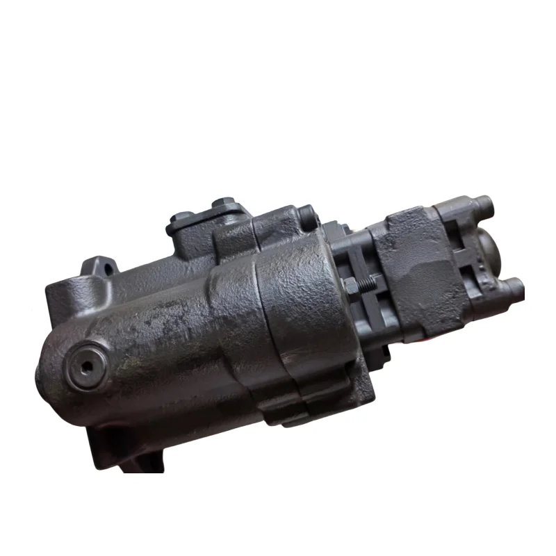
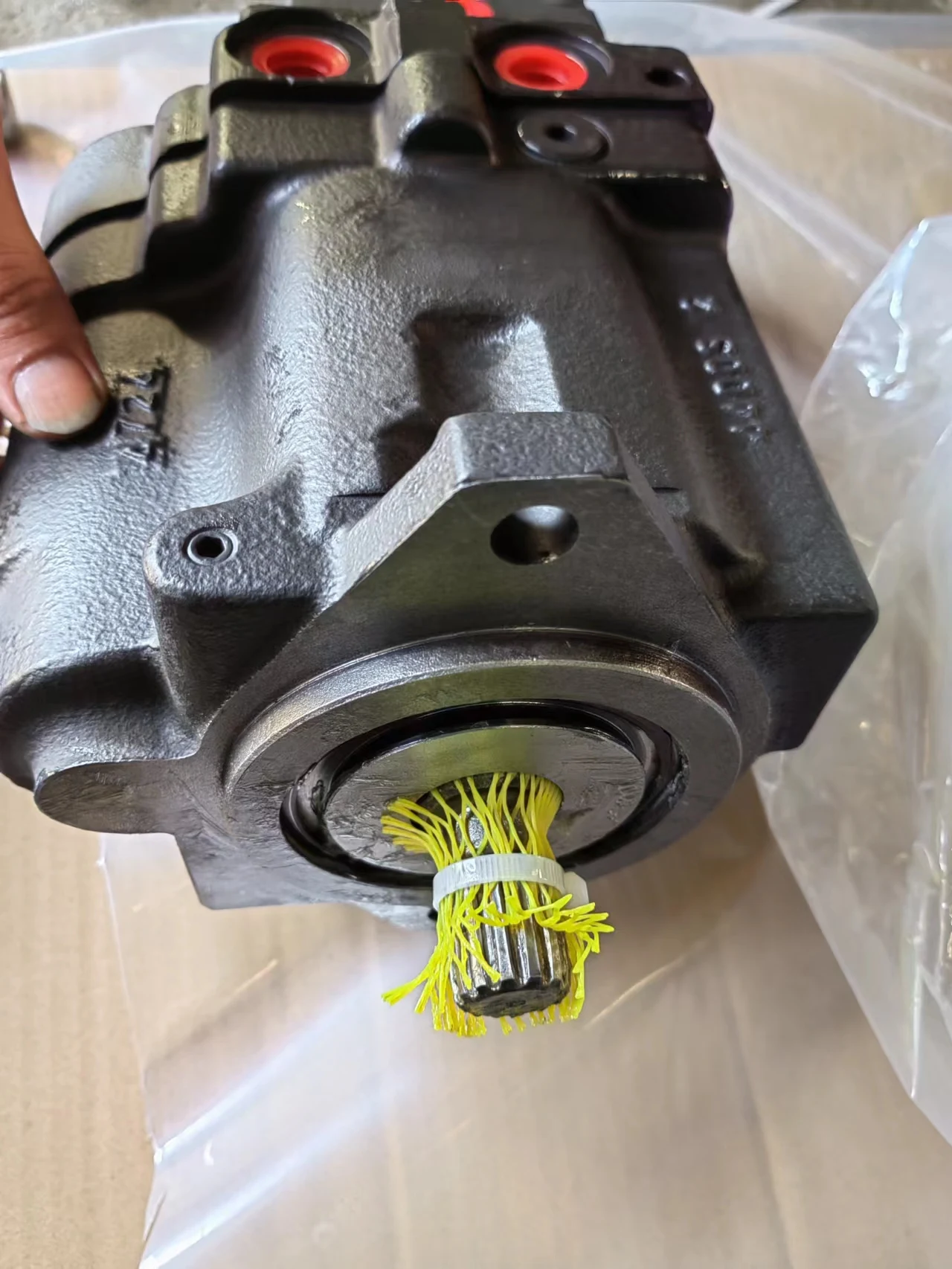
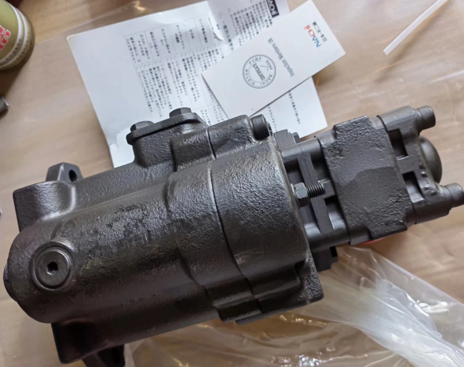
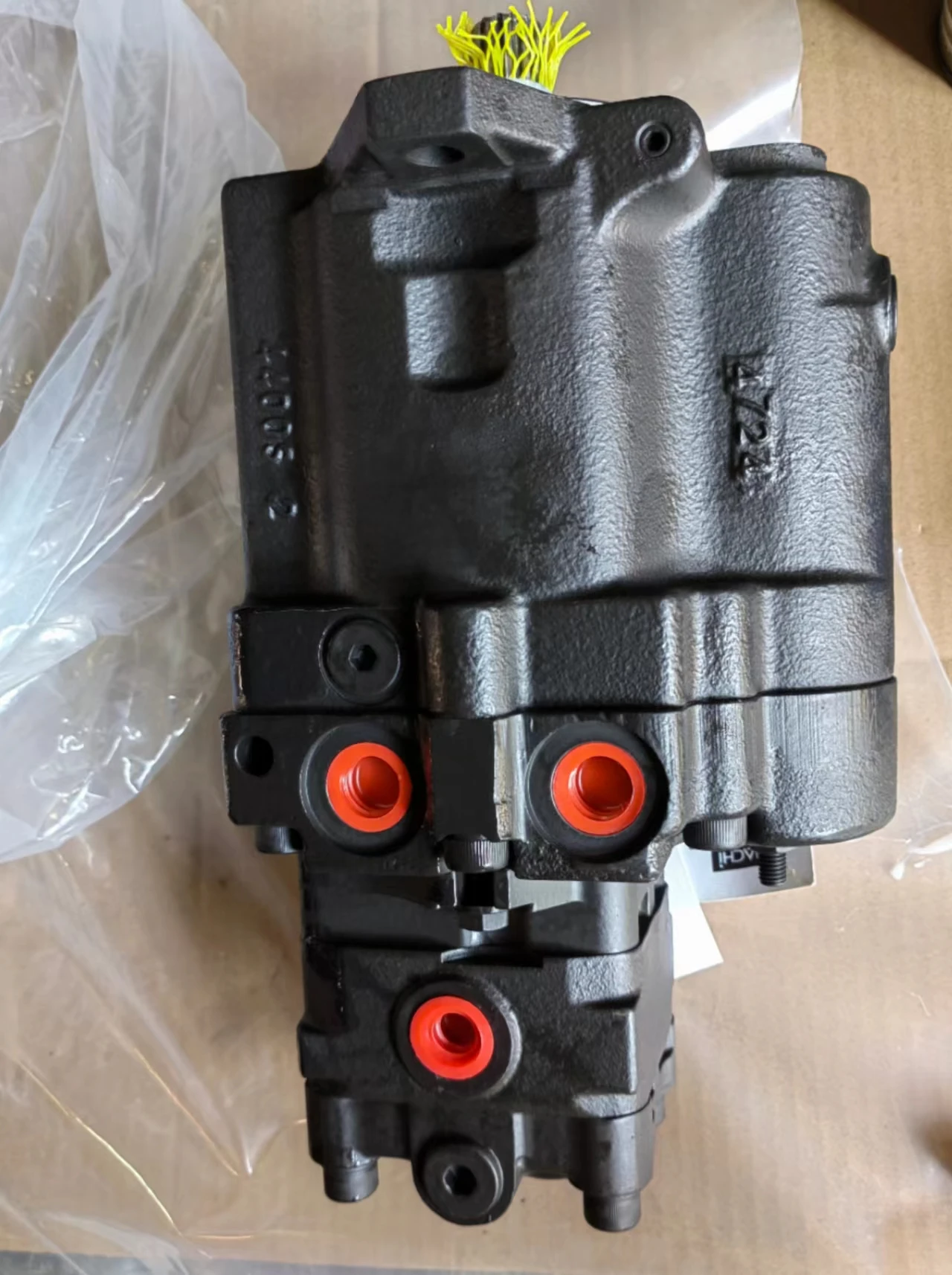
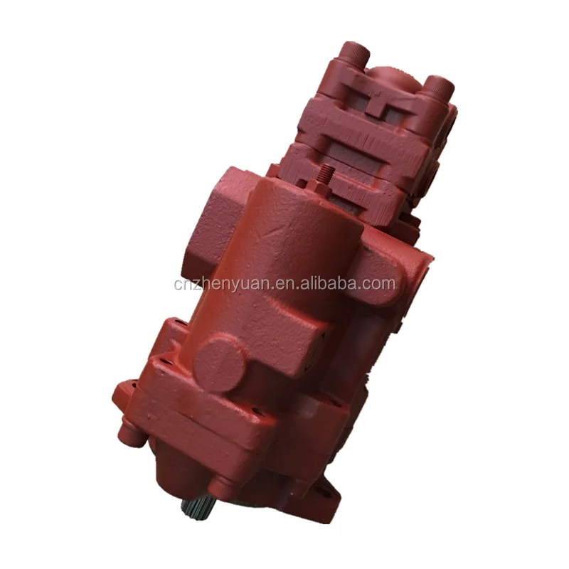
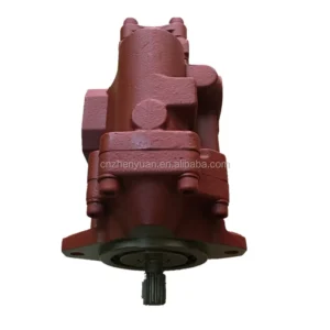


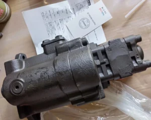
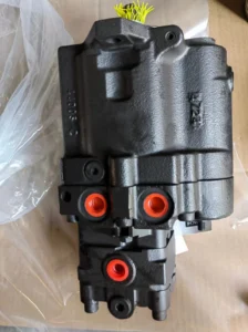

PVD PVD-00B PVD-1B PVD-2B PVD-3B PVD-15B Original piston Pump PVD-15B-32BP-9AG5-4634G high pressure hydraulic pump
Displacement and pressure performance•
Displacement specification: Swashplate variable piston pump, theoretical displacement 15 mL/r (mL/ RPM), supports manual variable adjustment, displacement adjustment range 0-15 ml /r, suitable for medium and small flow medium and high pressure hydraulic systems, variable response speed ≤0.5 seconds.
•
Pressure rating: Continuous working pressure 25 MPa (250 bar), instantaneous peak pressure 31.5 MPa (315 bar), single duration ≤10 seconds, capable of withstanding heavy-load impact loads, pressure fluctuation error ≤±0.3 MPa.
•
Flow output: At the rated speed of 1500 rpm, the maximum flow rate is 13.05 L/min (15 mL/r×1500 rpm× volumetric efficiency 92%). Under the working condition of 2000 rpm, the flow rate is 17.4 L/min. When the variable is adjusted, the flow rate changes linearly with the displacement, and the flow pulsation rate is ≤3%.
2. Rotational speed and structural parameters
•
Speed range: Minimum speed 600 rpm, maximum speed 2500 rpm, compatible with 4-pole asynchronous motor (1450 rpm) and diesel engine power source. The stability error at low speed is ≤±2%, and the vibration at high speed is ≤2.5 mm/s.
•
Structural type: Axial swash plate variable piston pump, featuring a “7-piston uniform distribution + manual variable mechanism” design. The piston diameter is 12mm, the stroke is 10mm, the maximum inclination Angle of the swash plate is 18°, and the distribution plate is made of bimetallic composite material (steel base + copper alloy liner), which has self-lubricating properties.
•
Core material The pump body is made of high-strength aluminum alloy (6061-T6, tensile strength ≥310 MPa), the plunger is made of stainless steel (304, surface roughness Ra0.2, mirror-polished), and the swash plate is quenched with 40Cr (surface hardness HRC55-58, carburized layer thickness 0.8-1.2 mm). The sealing element is a combination seal of polytetrafluoroethylene and nitrile rubber (with a temperature resistance range of -30℃ to 120℃).
3. Installation and oil port specifications
•
Installation method: Flange installation (4-hole positioning), in compliance with SAE C standard, positioning pin diameter Φ 12mm, installation center distance 150× 110mm, suitable for small and medium-sized hydraulic power units, supports horizontal installation, installation surface flatness ≤ 0.05mm /m.
•
Oil port dimensions: Suction port G1.5 (internal thread, precision ISO 228-1), pressure port G1 (internal thread), drain port G1/4 (internal thread), compatible with DN25-DN32 hydraulic pipelines. The suction port can be customized with flange connection (compatible with PN16 flange standard) to enhance oil flow capacity.
•
Weight and dimensions: The overall weight of the machine is 30 kg, with a length × width × height of 270×190×160 mm. The pump core is centrally arranged, with a center of gravity offset of no more than 5 mm, which is convenient for integration into equipment with limited space.
4. Oil and environmental requirements
•
Oil type: L-HM 46 anti-wear hydraulic oil is recommended. L-HV 46 hydraulic oil should be selected for low-temperature environments (below -20℃). It is compatible with phosphate ester flame-retardant hydraulic fluid. The kinematic viscosity range of the oil is 18-300 mm²/s, and the acid value of the oil is ≤0.05 mgKOH/g.
•
Cleanliness standard: ISO 4406 16/13 grade (NAS 7 grade). A 100 μm oil filter (filtration flow rate ≥ twice the pump flow rate, pressure drop ≤0.05 MPa) should be installed at the oil suction port. A 10-20 μm fine filter should be added at the oil return port. It is recommended to add a pressure pipeline filter (filtration accuracy 10 μm) in the high-pressure circuit.
•
Working environment: Ambient temperature -25℃ to 80℃, relative humidity ≤95% (no condensation), adaptable to vibration (vibration acceleration ≤10 m/s²) and oil contamination conditions, protection grade IP54, avoid long-term exposure to environments with dust concentration > 10 mg/m³.
Ii. Working Principle
This pump is an axial swash plate type variable piston pump. It achieves high-pressure hydraulic energy output through the core mechanism of “swash plate driving the piston to reciprocate – periodic change of cylinder cavity volume – distribution plate changing of inlet oil”. The variable mechanism can adjust the displacement in real time to meet the load requirements. The specific process is as follows:
Power transmission and plunger drive
The power source drives the pump shaft to rotate through an elastic coupling. The pump shaft drives the cylinder to rotate synchronously. Under the combined action of centrifugal force and the return disc spring, the ball heads of the 7 evenly distributed plungers in the cylinder are always in close contact with the end face of the swash plate (contact pressure ≤5 MPa). The swash plate and the cylinder block have an adjustable inclination Angle (0-18°). When the cylinder block rotates, the inclined profile of the swash plate forces the plunger to perform reciprocating linear motion in the cylinder block hole, and the stroke varies linearly with the inclination Angle of the swash plate.
2. Suction oil circulation and variable regulation
•
Oil absorption stage When the plunger rotates with the cylinder block to the “lower inclined plane” area of the swash plate, it extends outward under the action of the spring force of the return disc. The volume of the sealed cavity in the cylinder block hole gradually increases, and the pressure inside the cavity drops to 0.02-0.05 MPa (absolute pressure), forming a local vacuum. The oil in the fuel tank enters the cavity through the oil suction pipeline and the oil suction window of the distribution plate (with a flow area of ≥ 150mm ²), completing the oil suction process. The oil suction efficiency is ≥98%.
•
Oil pressing stage When the plunger rotates to the “upper inclined plane” area of the swash plate, the inclined plane of the swash plate exerts axial pressure on the plunger through the ball joint, forcing the plunger to retract into the cylinder. The volume of the sealed cavity is sharply reduced, and the oil in the cavity is pressurized to the rated pressure (25 MPa), and then output to the hydraulic system through the oil pressure window of the distribution plate and the oil pressure pipeline, completing the oil pressure process. The oil pressure efficiency is ≥95%.
•
Variable adjustment: Manually rotate the variable handle to adjust the variable mechanism and change the tilt Angle of the swash plate. When the tilt Angle increases, the reciprocating stroke of the plunger increases, and the displacement increases linearly. When the tilt Angle decreases (up to 0°), the stroke shortens and the displacement linearly decreases (up to 0), achieving stepless adjustment of the flow rate from 0 to 13.05 L/min (1500 rpm), adapting to the dynamic changes in the load flow demand.
3. Sealing and flow distribution guarantee
The distribution plate and the end face of the cylinder block adopt a precise fit design (axial clearance 0.01- 0.03mm), combined with the high-pressure oil film self-sealing effect, effectively isolating the oil suction chamber from the oil pressure chamber, with an internal leakage of ≤ 0.3L /min (rated working condition). The plunger and the cylinder block hole adopt clearance sealing (fit clearance 0.005- 0.01mm), and form a dynamic sealing oil film by means of the viscosity of the oil, ensuring high-pressure sealing performance while reducing wear (wear amount ≤ 0.005mm /1000 hours). When the variable mechanism is adjusted, the distribution plate adaptively adjusts the end face contact pressure through pressure feedback to ensure the continuous and stable circulation of the suction oil.
Iii. Product Features and Advantages
High voltage, high precision and high energy efficiency
It adopts a 7-plunger uniform distribution + bimetallic distribution plate design, with a continuous working pressure of up to 25 MPa, far exceeding the pressure grades of gear pumps (≤16 MPa) and vane pumps (≤21 MPa). The precise fit between the plunger and the cylinder block hole enables a volumetric efficiency as high as 90%-95% (under rated conditions), saving 20%-25% energy compared to gear pumps of the same displacement, and reducing the annual operating energy consumption by approximately 8,000 kWh. The flow pulsation rate is ≤3%. When combined with a pressure compensation valve, it can achieve a pressure control accuracy of ± 0.5MPa, making it suitable for high-precision scenarios such as hydraulic forming and precision pressing.
2. The variables are flexible and have strong load adaptability
The manual variable mechanism supports stepless adjustment of displacement from 0 to 15 mL/r, with a regulating torque of ≤15 N·m. It can adjust the output flow in real time according to load changes, avoiding energy waste caused by “a big horse pulling a small cart”. The swash plate tilt Angle adjustment range is wide (0-18°), and the flow regulation response time is ≤0.5 seconds. It is suitable for scenarios with frequent load fluctuations such as amplitude variation in construction machinery and injection molding machine injection, and the operation efficiency is increased by 15%-20%.
3. High reliability and long service life
The plunger is made of 304 stainless steel with mirror polishing treatment (surface roughness Ra0.2), and is matched with a 40Cr quenched swash plate (surface hardness HRC55-58), with a wear coefficient as low as 0.0015. The return disc spring is made of fatigue-resistant alloy material (elastic limit ≥1200 MPa), with a cycle life of over 10 million times. The fault-free operating life under rated conditions reaches 12,000 hours, which is 50% longer than that of ordinary vane pumps and 20% longer than that of conventional plunger pumps.
4. Wide adaptability and environmental tolerance
The polytetrafluoroethylene + nitrile rubber combination seal is compatible with various media such as anti-wear hydraulic oil and flame-retardant hydraulic fluid, and is suitable for special fire prevention scenarios such as metallurgy and coal mines. The starting torque increases by no more than 30% in a low-temperature environment of -25℃, with no jamming phenomenon, and it can operate stably in cold regions. The IP54 protection grade, combined with the anti-corrosion treatment of the aluminum alloy pump body, can adapt to harsh industrial working conditions such as vibration and oil stains.
Iv. Usage Functions and Purposes
1. Core usage functions
•
High-pressure power output: It provides a stable pressure oil of 25 MPa for medium and high-pressure actuating components (such as high-pressure hydraulic cylinders and hydraulic motors), driving heavy-duty actions such as extrusion, lifting, and excavation. A single pump can meet the requirements of actuating components with a power of ≤55 kW, and the power transmission efficiency is ≥90%.
•
Stepless variable fuel supply: By adjusting the swash plate Angle, the flow rate can be steplessly changed from 0 to 13.05 L/min (1500 rpm), which is suitable for multi-speed operation scenarios such as “fast advance – working advance – fast retreat”, reducing system throttling losses and increasing operation efficiency by 15% to 20%.
•
Precision pressure control: When used in conjunction with relief valves or pressure compensation valves, it can achieve a pressure regulation accuracy of ± 0.5MPa, which is suitable for processes with high requirements for pressure control accuracy such as hydraulic forming, precision pressing, and hydraulic chuck clamping. The product qualification rate is increased by 5% to 8%.
2. Main application fields
•
Construction machinery: Bucket excavation drive for small excavators under 5 tons, steering system for loaders, high-pressure hydraulic source for lifting mechanisms of electric forklifts, suitable for frequent start-stop and load impact conditions.
•
Industrial manufacturing equipment: Injection mechanisms for small and medium-sized injection molding machines, pressing systems for presses under 100 tons, and precision hydraulic chuck clamping devices for CNC machining centers, meeting the requirements of high-precision and high-stability operations.
•
Metallurgical and mining equipment: Small rolling mill press-down devices, auxiliary action drives for mine roadheaders, hydraulic valve control for mineral processing equipment, suitable for medium and high pressure, dusty working conditions.
•
Special equipment: Hydraulic wrench power source, small aerospace parts forming equipment, small hydraulic steering gear drive for ships, suitable for high-pressure and precise control scenarios.
V. Applicable Machines and Scenarios
1. Adapt to the core machine
•
Construction machinery: Small excavators under 5 tons (such as mini excavators), small loaders (≤3 tons), electric forklifts (≤5 tons).
•
Industrial equipment: Small and medium-sized injection molding machines (clamping force ≤500 tons), 100-ton presses, CNC machining centers (hydraulic chuck diameter ≤ 200mm).
•
Heavy industrial equipment: small rolling mills (rolling width ≤ 500mm), tunnel boring machines (diameter ≤ 1.5m), flotation machines for mineral processing (volume ≤ 5m ³).
•
Specialized equipment: Hydraulic wrench (torque ≤2000 N·m), precision forming machine (forming accuracy ≤± 0.02mm), small steering gear for ships (torque ≤500 N·m).
2. Typical application scenarios
•
Excavator excavation operation: At a speed of 1500 rpm, it outputs a flow rate of 13.05 L/min, driving the bucket hydraulic cylinder to achieve 25 MPa pressure excavation. The excavation force reaches 80 kN, and the single excavation cycle time is ≤3 seconds. It is suitable for small and medium-sized earthwork projects and municipal construction scenarios.
•
Precision pressing process: At 1200 rpm, the flow rate is adjusted to 8 L/min through a variable mechanism, providing a stable pressure of 25 MPa for a 100-ton press. The pressing accuracy is ≤± 0.02mm, making it suitable for precision forming scenarios of automotive parts (such as brake pads) and electronic components.
•
Low-temperature outdoor operations: In open-pit mines at -20℃ or winter construction scenarios in northern regions, L-HV 46 hydraulic oil is selected. After the pump body starts, the oil temperature rises above 5℃ within 3 minutes, driving the roadheaders to perform auxiliary actions (such as lifting and lowering of the scraper). It can operate continuously for 8 hours without pressure fluctuations or jamming.
•
Injection molding machine injection operation: At a speed of 1500 rpm, a three-stage oil supply of “fast feed (13.05 L/min) – working feed (5 L/min) – holding pressure (2 L/min)” is achieved through variable adjustment. The injection pressure is 25 MPa, and the holding pressure accuracy is ±0.3 MPa, which is suitable for the precision injection molding scenarios of plastic parts.
Six. Similar models
1. Alternative models of the same series
•
PVD-10B-32BP-9AG5-4634G: Theoretical displacement 10 mL/r, continuous pressure 25 MPa, flow rate 8.7 L/min at 1500 rpm, volumetric efficiency 90%-95%, installation dimensions fully compatible with the original model, suitable for low-flow high-pressure scenarios (such as hydraulic wrenches, small servo motors).
•
PVD-20B-32BP-9AG5-4634G: Theoretical displacement 20 mL/r, continuous pressure 25 MPa, flow rate 17.4 L/min at 1500 rpm. The structural form is consistent with the original model and is suitable for high-flow and high-pressure systems (such as 10-ton loaders, 200-ton presses).
2. Cross-series alternative models
•
PV2R-15-4634: A vane-plunger composite structure pump with a displacement of 15 mL/r and a continuous pressure of 16 MPa. It features a simple structure and low cost (30% lower than the original model), making it suitable for low-pressure and high-pressure mixed scenarios (such as ordinary machine tool hydraulic systems and small conveying equipment).
•
A4VSO-18-4634: High-pressure axial piston pump, displacement 18 mL/r, continuous pressure 31.5 MPa, featuring an electronically controlled variable mechanism (response time ≤0.3 seconds), suitable for high-precision closed-loop control scenarios (such as aerospace component testing equipment, precision hydraulic servo systems).
Vii. Precautions for Use
1. Oil and fluid management norms
•
It is mandatory to use L-HM 46 or L-HV 46 anti-wear hydraulic oil. Different grades and types of oil must not be mixed. The first oil change cycle is 500 hours, and it should be changed every 1000 hours thereafter. Before the oil change, the pipelines and oil tank should be flushed with new oil (the flushing oil volume should be ≥ twice the system volume), and the cleanliness of the oil after flushing should reach ISO 4406 17/14 grade.
•
The suction oil filter should be replaced immediately when the pressure difference exceeds 0.2 bar. The return oil filter should be inspected every 500 hours and replaced when the contamination level exceeds ISO 4406 18/15 grade. The moisture content (≤0.05%) and acid value (≤ 0.1mgKOH /g) of the oil should be tested monthly. When they exceed the standards, dehydration or oil change is required to prevent rust and wear of the plunger and distribution plate.
2. Installation and commissioning requirements
•
The connection is made by elastic couplings. The coaxiality error between the pump shaft and the motor shaft is ≤ 0.1mm (radial), and the angular error is ≤0.2°. It is strictly prohibited to directly install transmission components such as pulleys and sprockets on the pump shaft (the radial bearing capacity of the pump shaft is ≤ 500N) to avoid uneven wear of the cylinder body and plunger jamming.
•
The diameter of the oil suction pipeline is ≥Φ


