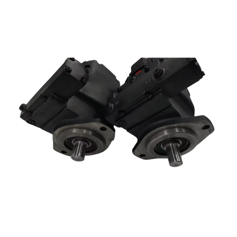
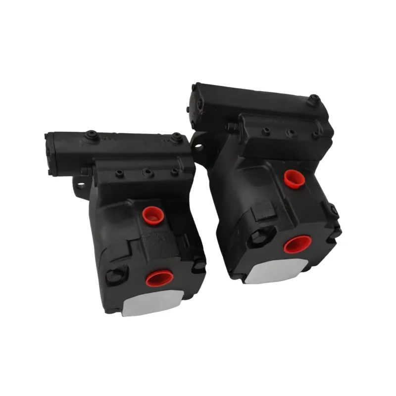
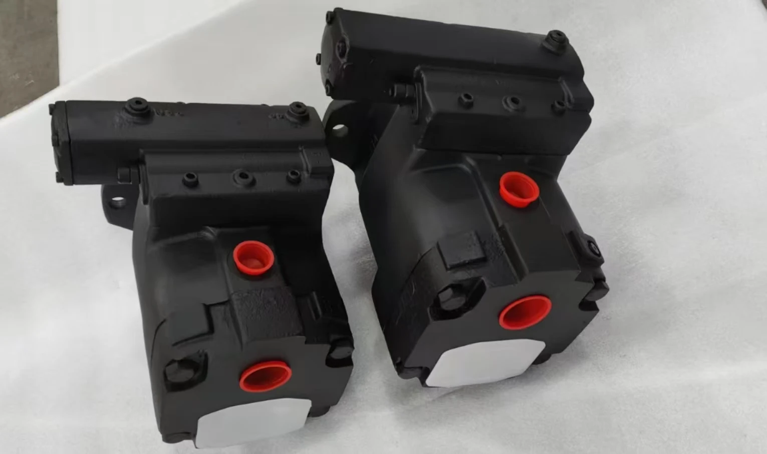
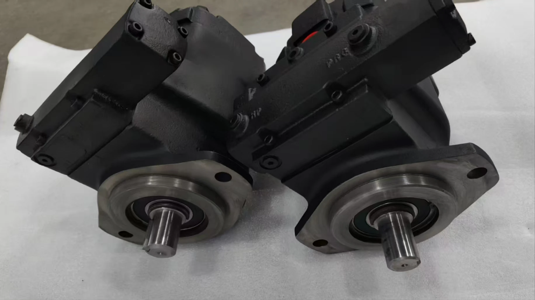
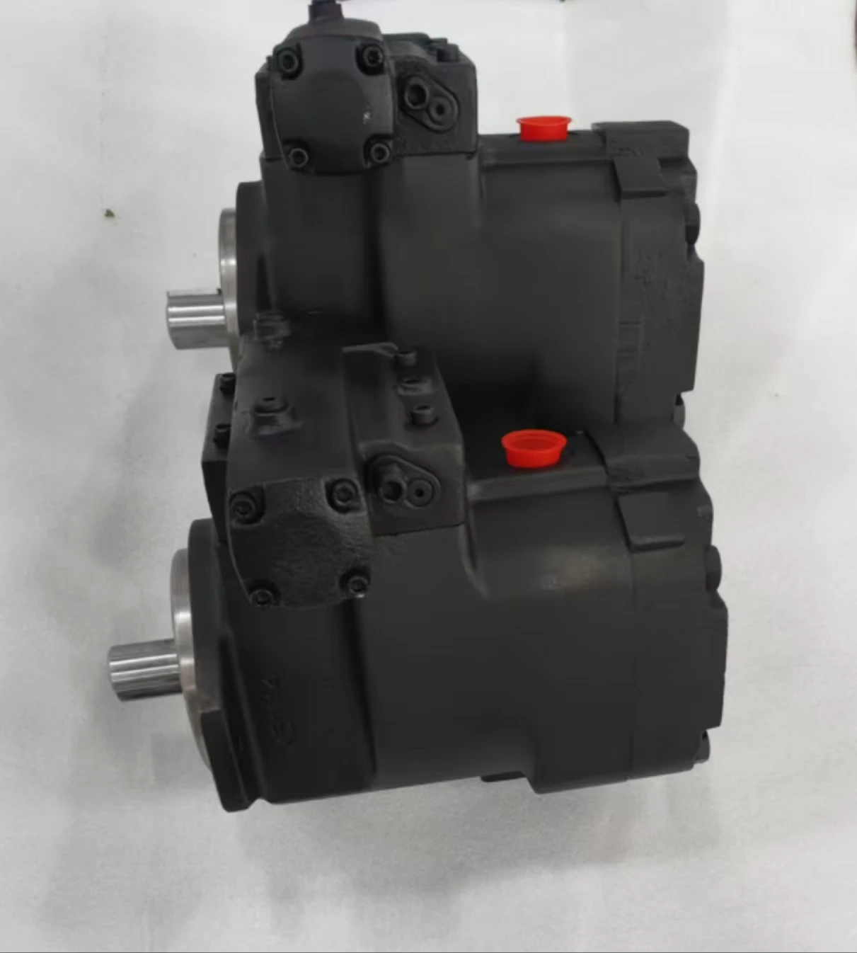
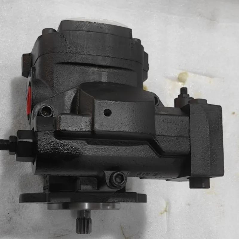
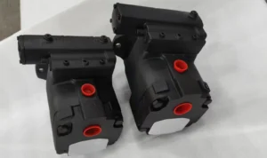

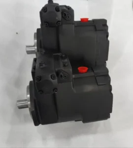
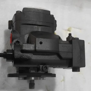
Hydraulic Oil Pump PVWJ PVWH PVWW PVWC PVWJ-098 Series PVWJ-098-A1UV-LDFY-P-1NNNN-CP Axial Variable Piston Pump
•
Displacement: The “098” in the model corresponds to a theoretical displacement of 98.3 mL/r, which is a medium to large-sized displacement specification and is suitable for medium and high-pressure high-flow working conditions.
•
Working pressure: It adopts an open circuit design, with a rated working pressure of 210 bar (21 MPa) and a peak pressure of up to 250 bar (25 MPa), which can stably adapt to medium and high-pressure load scenarios.
•
Speed range: Rated speed 1800 rpm, maximum speed 2100 rpm, minimum stable speed no less than 80 rpm, compatible with continuous operation at medium and high speeds and smooth operation at low speeds.
•
Control mode: Integrated load sensitivity (LS) and pressure compensation dual control, supporting real-time adjustment of displacement according to system load pressure. The “LDFY” identifier corresponds to the flow priority control logic and can be adapted to scenarios where multiple execution components work collaboratively.
•
Structural form: Single-cylinder swash plate axial piston structure. The “CP” marking corresponds to the cast iron pump body configuration, enhancing the shock and vibration resistance performance.
•
Oil requirements: Anti-wear hydraulic oil with viscosity ranging from 15 to 400 mm²/s is suitable. The working oil temperature range is from -20℃ to 80℃, and the oil cleanliness must reach NAS level 8 (ISO 18/14).
•
Installation and adaptation: The shaft ends are connected by flat keys, and the shaft diameter complies with the ISO 3019-2 standard. The flange connection complies with the SAE J518C specification. The oil port is arranged at the tail end to meet the integration requirements of the conventional power end.Ii. Working Principle
This plunger pump is an open-circuit swash plate axial plunger pump. Its core components include the drive shaft, cylinder block, plunger, swash plate, oil distribution plate and load-sensitive control valve group. During operation, the prime mover drives the drive shaft to rotate the cylinder block. Under the action of centrifugal force and the return disc, the spherical end of the plunger inside the cylinder block always closely adheres to the surface of the swash plate. Due to the inclination Angle between the swash plate and the cylinder block axis, when the plunger rotates with the cylinder block, it moves back and forth along the cylinder bore. When the plunger rotates to the high side of the swash plate, it is squeezed and moves towards the interior of the cylinder block. The volume of the sealed cavity decreases, and the oil pressure increases. The oil is then discharged to the system through the oil distribution plate’s oil discharge window, completing the oil pressure. When the plunger rotates to the lower side of the swash plate, it extends outward under the action of the return force, increasing the volume of the cavity and creating a vacuum. The oil in the oil tank is then drawn in through the suction window of the oil distribution plate, completing the oil suction process.
The load-sensitive control mechanism detects the system load pressure in real time through a pressure sensor. When the load increases, the control valve pushes the swash plate to increase the tilt Angle, the plunger stroke extends, and the displacement increases. When the load decreases, the tilt Angle of the swash plate reduces, and the displacement decreases, achieving a precise match between the flow rate and the load. The pressure compensation function serves as an auxiliary measure. When the system pressure reaches the set value, it automatically limits the increase in displacement to prevent overpressure operation and ensure system safety.
Iii. Product Features and Advantages
•
High efficiency and energy saving: With dual control of load sensitivity and pressure compensation, the volumetric efficiency can reach over 95%, and the total efficiency exceeds 90%. It can effectively reduce energy waste in scenarios of “large flow and small load” and lower system temperature rise.
•
Strong impact resistance: The cast iron pump body structure corresponding to the “CP” logo has a higher strength than the conventional aluminum alloy pump body. Combined with the reinforced bearing design, its service life is increased by more than 30% in the scenarios of construction machinery or mining with intense vibration.
•
High control accuracy: The flow priority control logic (LDFY) can precisely allocate the fuel supply flow of multiple actuating components, avoiding action interference, and is particularly suitable for automated equipment with multi-process collaborative operations.
•
Compact structure and good adaptability: It adopts an integrated valve group design, with a volume 20% smaller than that of traditional pumps of the same displacement. The arrangement of the oil port at the tail saves installation space and can be directly adapted to the power compartment of equipment with limited space.
•
Low maintenance cost: It adopts a modular pump core design. After wear, the pump core assembly can be replaced separately without disassembling the entire pump body. The key seals are made of fluororubber, which is oil-resistant and aging-resistant, and the replacement cycle is extended to over 2,000 hours.
Iv. Usage Functions and Purposes
1. Usage function
As the power core of the hydraulic system, it converts the mechanical energy of the prime mover (motor, engine) into the pressure energy of hydraulic oil, providing medium and high-pressure oil for the actuating components such as hydraulic cylinders and hydraulic motors, and driving the equipment to achieve linear or rotational movements such as lifting, rotating, squeezing and pushing. Through the coordinated control of load sensitivity and pressure compensation, dynamic flow distribution and pressure protection for multiple actuating elements are achieved, ensuring the system’s action coordination and operational safety under complex working conditions.
2. Uses
It is widely applied in medium and high-pressure open hydraulic systems, covering fields such as industrial manufacturing, construction machinery, metallurgical processing, petrochemicals, and agricultural machinery. It provides stable power for the core working mechanisms of equipment, especially suitable for complex systems where multiple actuating elements work in coordination.
V. Applicable Machines and Scenarios
1. Applicable machines
•
Industrial equipment: Medium-sized injection molding machines (500-1000 tons), hydraulic presses, metal cutting machines, glass forming machines, woodworking multi-process machining centers.
•
Construction machinery: 15-25 ton class loaders, small excavators, crawler cranes, auxiliary power units for hydraulic crushing stations.
•
Special equipment: Small port loading and unloading machines, tunnel lining machines, hydraulic suspension systems for large tractors, roller drive equipment for metallurgical production lines.
2. Applicable scenarios
It is suitable for medium and high pressure conditions, multi-actuator coordination, and large load fluctuations, such as multi-process stamping forming in factory automated production lines, material handling and lifting in construction, steel transportation and rolling in metallurgical workshops, and small-scale crushing and tunneling operations in mines. It is particularly suitable for continuous operation scenarios that have high requirements for equipment spatial layout, operational efficiency and anti-vibration performance.
Six. Similar models
This model belongs to the PVWJ series of open circuit axial piston pumps. Similar models are mainly distinguished by displacement, control mode and pump body material. Common ones include:
•
Pvwj-076-a1uv-ldfy-p-1nnn-cp: Displacement 76.5 mL/r, rated pressure 210 bar, control mode consistent with the target model, suitable for small flow medium and high pressure systems.
•
Pvwj-130-a1uv-ldfy-p-1nnn-cp: Displacement 130.2 mL/r, rated pressure 210 bar. It is a high-flow model in the same series and is suitable for high-flow open systems.
•
Pvwj-098-a1uv-rdfy-p-1nnn-al: Consistent with the displacement and pressure of the target model, it adopts an aluminum alloy pump body (AL) + pressure priority control (RDFY), suitable for scenarios with light loads and weight sensitivity.
•
Similar alternative model: PVG-098 series open piston pump. The structure and principle are the same, but the pressure rating has been increased to 250 bar, making it suitable for working conditions with higher pressure requirements.
Vii. Precautions for Use
•
Oil management specifications: Select anti-wear hydraulic oil with a viscosity of 20-200 mm²/s. It is strictly prohibited to mix oils of different brands. A ≥100 μm screen filter is installed at the oil suction port, and a 25 μm fine filter is added to the return oil pipeline. The contamination degree of the filter element is checked every 500 hours, and the hydraulic oil is replaced and the oil tank is cleaned every 2000 to 3000 hours.
•
Installation accuracy requirements: Connect to the prime mover with an elastic coupling. The coaxiality error of the two shafts should be ≤ 0.1mm, and the angular error should be ≤0.5°. The length of the oil suction pipeline should be no more than 1.5m, and its diameter should not be less than the diameter of the pump’s oil suction port to avoid excessive oil suction resistance causing cavitation.
•
Start-up and operation monitoring: Before the initial start-up, fill the pump body with clean hydraulic oil and manually turn the wheel 3 to 5 times to confirm there is no jamming. When starting, run it at low speed (800 rpm) without load for 10 minutes. After the oil temperature rises above 30℃, gradually load it. During operation, monitor the oil temperature (30-65℃ is the best, and the maximum should not exceed 80℃) and pressure (it is strictly prohibited to exceed the rated pressure for a long time). Stop the machine immediately if any abnormal noise or leakage occurs.
•
Maintenance and care nodes: Check the shaft seal leakage every 1000 hours (allowable ≤3 drops per minute), and replace the sealing parts in time if the leakage exceeds the standard. Disassemble and inspect the pump core friction pair every 3,000 hours. If the wear exceeds 0.03mm, maintenance is required. Before a long-term shutdown (exceeding 30 days), drain the oil or inject anti-rust oil and seal the oil port.
•
Control parameter setting: The parameters of the load sensitive valve and the pressure compensation valve must be set by professionals according to the working conditions. Arbitrary adjustment is strictly prohibited. After replacing the control module, calibration is required to ensure the accuracy of flow distribution and avoid interference in the actions of the actuating elements.


