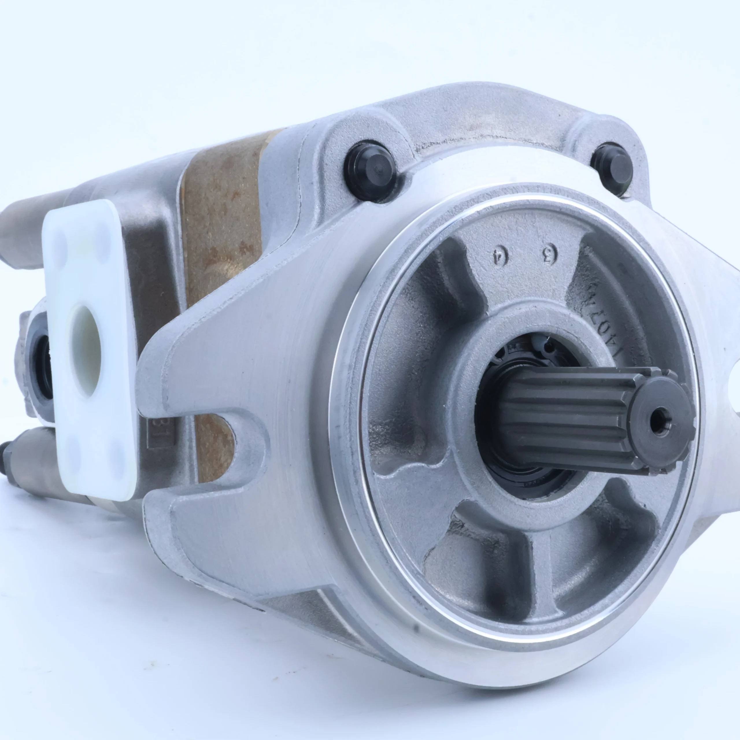

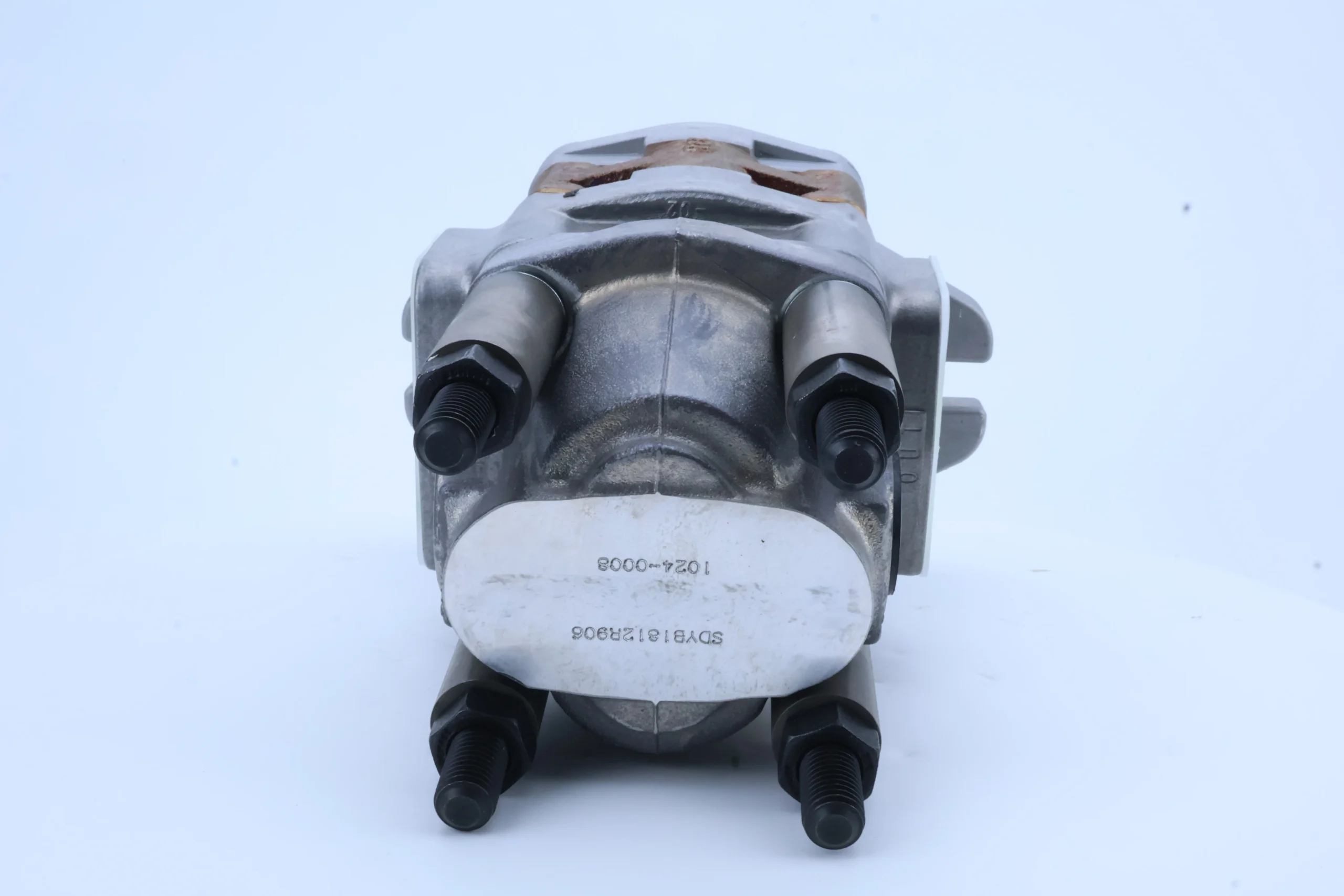
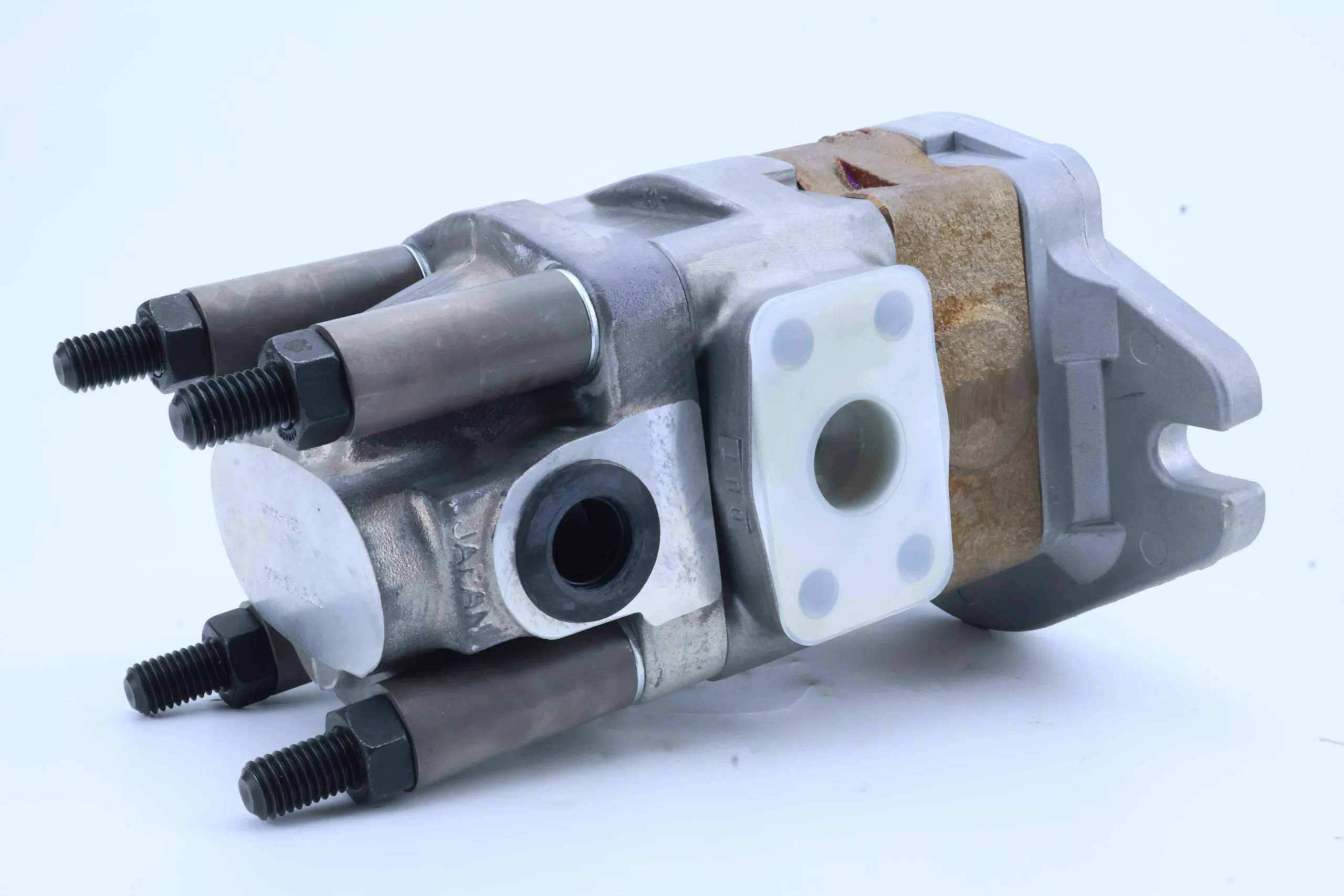
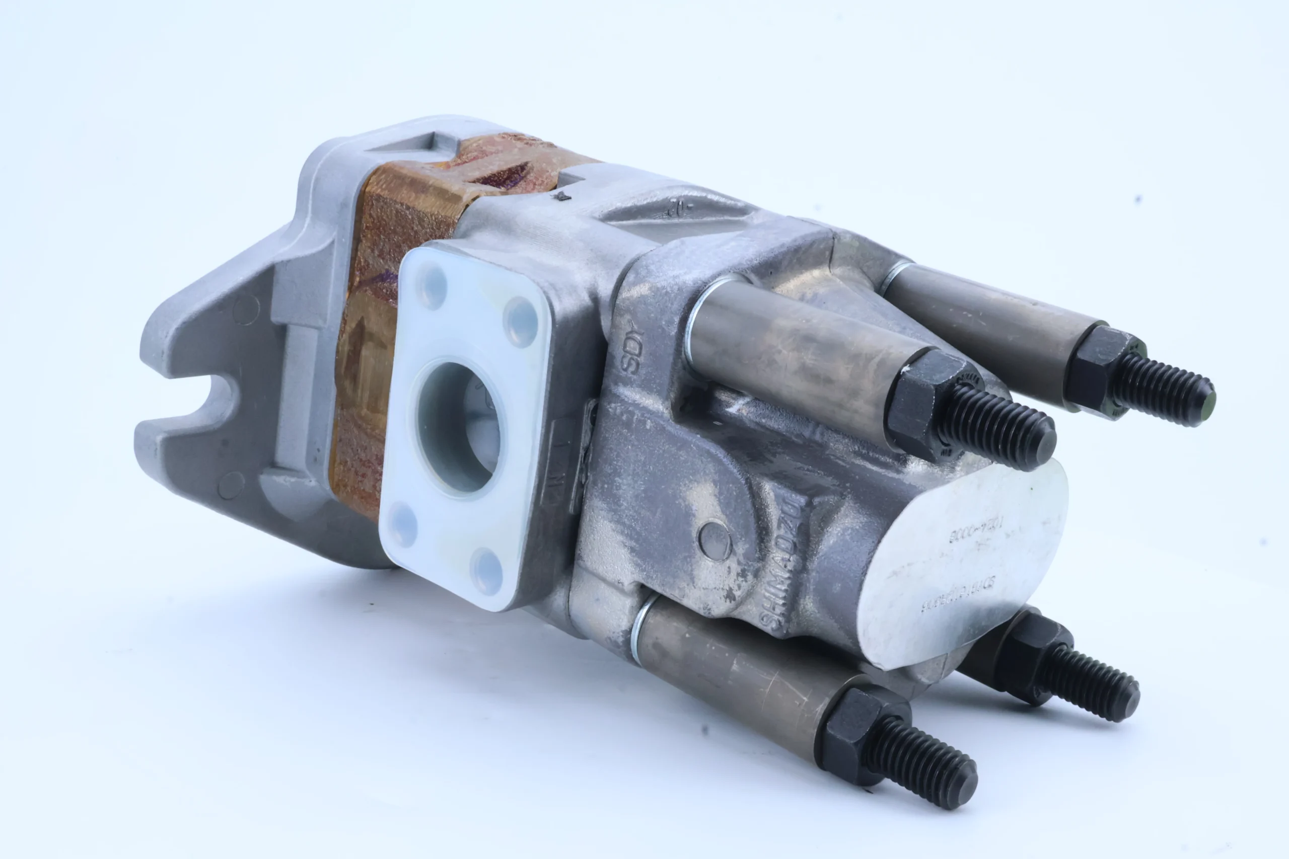
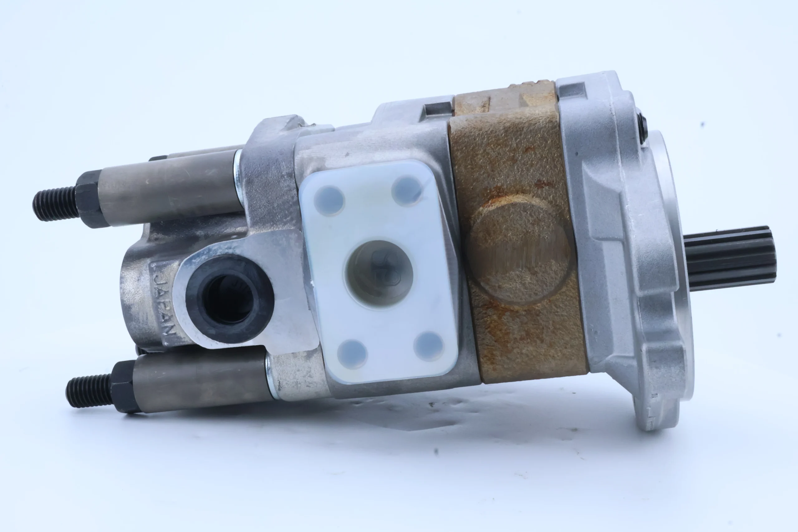
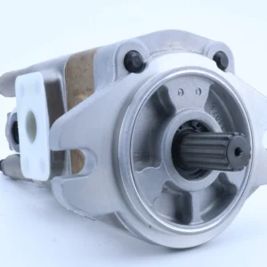
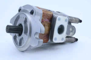

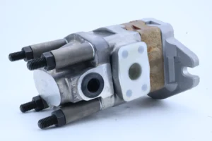

SDYB1812R906 Original Forklift Hydraulic Oil Pump SDYB SDB SDY SGP SGP1 SGP2 High Pressure Hydraulic Gear Pump
Core performance parameters
•Displacement specification: External meshing fixed displacement gear pump, theoretical displacement 18 mL/r (ml/RPM), actual displacement affected by volumetric efficiency, output range 15.3-16.2 L/min (at rated speed), flow output stability error ≤±3%, suitable for small low-pressure hydraulic systems.
•Pressure rating: Rated working pressure 16 MPa (160 bar), stable operation under continuous working pressure. The instantaneous peak pressure is 20 MPa (200 bar), with a single duration of no more than 5 seconds. It can withstand the load impact of small equipment. The set pressure of the relief valve is matched with the peak pressure.
•Flow output: At the rated speed of 1500 rpm, the rated flow rate is 23.0-24.3 L/min (18 mL/r×1500 rpm× volumetric efficiency 85%-90%). At 2000 rpm, the flow rate is 30.6-32.4 L/min. The flow rate varies linearly with the rotational speed, and the flow pulsation rate is ≤18%.
2. Rotational speed and power parameters•Speed range: The minimum stable speed is 600 rpm, the maximum allowable speed is 2000 rpm, compatible with small asynchronous motors (1450 rpm) and micro diesel engines (1800 rpm). There is no jamming at low speeds, and the vibration at high speeds is ≤2.5 mm/s.
•Efficiency indicators: Under rated working conditions, volumetric efficiency is 85%-90%, mechanical efficiency is 90%-95%, and total efficiency is 76.5%-85.5%. In the load range of 60% to 100%, the overall efficiency remains above 75%, and the energy consumption performance is suitable for small power systems.
•Power matching: At a rated speed of 1500 rpm and a rated pressure of 16 MPa, the input power is approximately 6.2 kW, the output power is about 5.3 kW, and the input torque is approximately 40 N·m, which is suitable for the power transmission requirements of small power sources.
3. Structure and Physical Parameters
•Structural type: External meshing involute gear pump, featuring a double-gear meshing design of “driving gear + driven gear”, with a gear module of 1.5, 12 teeth, and a tooth width of 10mm. It is equipped with an axial clearance compensation mechanism (clearance ≤ 0.06mm) to enhance volumetric efficiency.
•Core material The pump body is made of high-strength gray cast iron (HT250, tensile strength ≥250 MPa), the gears are alloy structural steel (20CrMnTi, carburized and quenched, surface hardness HRC58-62, carburized layer thickness 0.6-0.8mm), and the shaft is 40Cr quenched and tempered (hardness HRC28-32). The seal is made of nitrile rubber (with a temperature resistance range of -20℃ to 100℃).
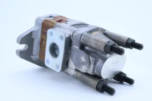
•Physical parameters: Net weight 3.2kg, external dimensions (length × width × height) 200×120× 100mm, installation method is plate installation, compatible with SAE micro installation flange, oil suction port diameter Φ 20mm, oil outlet port diameter Φ 15mm.
4. Medium and Environmental requirements
•Medium requirements: It is recommended to use L-HM 46 anti-wear hydraulic oil. For low-temperature environments (below -15℃), L-HV 46 hydraulic oil should be selected. It is compatible with common mechanical oil (viscosity grade N46). The kinematic viscosity range of the oil is 20-300 mm²/s, and the acid value of the oil is ≤0.1 mgKOH/g.
•Cleanliness standard: The oil cleanliness is required to reach ISO 4406 18/15 grade (NAS 9 grade). An 80 μm coarse filter (filtration flow rate ≥ 1.5 times the pump flow rate, pressure drop ≤0.08 MPa) should be installed at the oil suction port, and a 20-30 μm filter should be added at the oil return port.
•Environmental parameters: Operating environment temperature -10℃ to 80℃, relative humidity ≤95% (no condensation), can adapt to slight vibration (vibration acceleration ≤ 8m /s²), oil contamination conditions, protection grade IP54, avoid long-term exposure to environment with dust concentration > 15mg /m³.
Ii. Working Principle
This pump is an external meshing quantitative gear pump. It converts mechanical energy into hydraulic energy through the core mechanism of “gear meshing volume change – suction pressure oil chamber isolation – forced oil delivery”, and realizes oil delivery by relying on the periodic change of the sealed cavity formed during gear rotation. The specific process is as follows:
1. Power transmission and gear meshing
The power source drives the pump shaft to rotate through a coupling. The pump shaft drives the driving gear to rotate synchronously. The driving gear and the driven gear achieve reverse rotation (opposite directions, same speed) through the meshing of the tooth surfaces. The teeth of the two gears, the inner wall of the pump body and the front and rear end covers jointly form multiple sealed cavities (each cavity has a volume of approximately 1.5 mL). The 12-tooth structure can form 12 independent sealed cavities, ensuring continuous oil transportation.
2. Suction oil circulation and volume compensation
•Oil suction stage: When the gear rotates to the oil suction port side, the gear teeth gradually disengage from meshing, the gap between the teeth increases, and the volume of the sealed cavity expands accordingly. The pressure inside the cavity drops to 0.03-0.05 MPa (absolute pressure), creating a vacuum. Under the action of atmospheric pressure, the oil in the oil tank enters the sealed cavity through the oil suction pipeline and the oil suction port, completing the oil suction process. The oil suction efficiency is ≥95%.
•Oil pressing stage When the oil-filled sealed cavity rotates with the gear to the oil pressure port side, the gear teeth start to mesh, and the gap between the teeth is squeezed and reduced by the adjacent gear teeth. The volume of the sealed cavity drops sharply, and the oil inside the cavity is forcibly squeezed, with the pressure rising to the rated pressure (16 MPa). The oil is then output to the hydraulic system through the oil pressure port and the oil pressure pipeline, completing the oil pressure process. The oil pressure efficiency is ≥90%.
•Volume compensation: An axial clearance compensation mechanism is adopted. Through the elastic element of the rear end cover, the compensation disc is pushed to closely adhere to the gear end face, keeping the axial clearance within 0.06mm and reducing the leakage of high-pressure oil into the oil suction chamber. Meanwhile, the oil film at the gear meshing point forms an auxiliary seal, further enhancing the volumetric efficiency.
3. Lubrication and cooling
During the rotation of the gear, some high-pressure oil enters the bearing cavity through the gap between the gear shaft and the bearing, providing lubrication for the rolling bearing (the amount of lubricating oil is ≥ 0.2L /min). The lubricated oil flows back to the oil suction cavity through the oil drain hole. Meanwhile, during the circulation of the oil in the pump body, the heat generated by the gear meshing is carried away, keeping the pump body temperature within a reasonable range (≤80℃) and ensuring the stability of continuous operation.
Iii. Product Features and Advantages
Compact and small in structure, it is suitable for small devices
It adopts a micro external meshing structure design, with an external dimension of only 200×120× 100mm, a net weight of 3.2kg, and a volume of 70% of that of a vane pump of the same displacement. It can be installed in the narrow space of small equipment. The plate installation method is compatible with micro installation flanges. It is convenient to install and does not require special installation tools, meeting the lightweight design requirements of small equipment.
2. Low pressure, high efficiency, and controllable cost
The parameter combination of a rated pressure of 16 MPa and a rated flow rate of 24 L/min is suitable for the vast majority of small low-pressure hydraulic systems and can replace micro vane pumps (with higher reliability) or plunger pumps (with lower cost) of the same flow rate. The manufacturing cost of the entire machine is 60% to 70% lower than that of the plunger pump with the same flow rate. When purchasing in bulk, the unit price advantage is significant, making it suitable for batch matching of small equipment.
3. High reliability, adaptable to harsh working conditions
The gears are treated with 20CrMnTi carburizing and quenching, with a tooth surface hardness of HRC58-62. They have excellent wear resistance. Under the condition that the oil cleanliness meets the standards, the trouble-free operation life can reach 6,000 hours. The gray cast iron pump body has strong impact resistance, can withstand slight mechanical collisions and vibrations, and is suitable for non-standardized working environments such as small construction machinery and agricultural machinery.
4. Wide media compatibility and good environmental adaptability
Nitrile rubber seals are compatible with various media such as anti-wear hydraulic oil and mechanical oil, and do not require special oil, reducing the cost of oil procurement during operation and maintenance. The operating temperature range of -10℃ to 80℃ can cover the working environment in the vast majority of regions in China. It can operate stably in both northern winters and southern summers without the need for additional heating or cooling devices.
Iv. Usage Functions and Purposes
1. Core usage functions
•Low-pressure power output: It provides 16 MPa stable pressure oil for small actuating components (such as micro hydraulic cylinders and small hydraulic motors), driving lifting, pushing, rotating and other actions. A single pump can meet the requirements of actuating components with a power of ≤6 kW, and the power transmission efficiency is ≥76.5%.
•Stable flow supply: As a quantitative pump, it outputs a stable flow at a fixed speed, making it suitable for small-scale scenarios with moderate requirements for flow stability (such as feeding small injection molding machines and driving micro conveyors). The flow fluctuation rate is ≤18%, and simple speed regulation can be achieved through a throttle valve.
•System overload protection: When used in conjunction with a relief valve, if the system pressure exceeds the peak pressure of 20 MPa, the relief valve opens to relieve pressure, preventing the gear surfaces of the pump body from wearing or breaking due to overload, and ensuring the safety of the entire hydraulic system.
2. Main application fields
•Small construction machinery: 1-3 ton small loader lifting mechanism, 0.5-1 ton micro excavator auxiliary actions (such as bulldozer shovels), 1-2 ton electric forklift lifting system, suitable for reciprocating or rotary actions of medium and small loads.
•Small industrial equipment: micro injection molding machine (clamping force ≤100 tons) feeding mechanism, small press (≤50 tons) pressing system, desktop hydraulic fixture drive unit, meeting the power requirements of low pressure and small flow.
•Agricultural and garden machinery: Small tractor suspension systems, hydraulic drive mechanisms for orchard pruners, and power units for plant protection machinery spray pumps, all suitable for intermittent power output requirements in agricultural operations.
•Specialized small equipment: Small hydraulic station (power ≤ 7.5kW) power source, medical device hydraulic drive device (such as small hydraulic operating table), micro robot hydraulic execution system, which can work independently with a single pump or be used in parallel with multiple pumps.
V. Applicable Machines and Scenarios
1. Adapt to the core machine
•Small-scale construction machinery: 1-3 ton small loaders, 0.5-1 ton mini excavators, 1-2 ton electric forklifts.
•Small industrial equipment: micro injection molding machines (clamping force ≤100 tons), small presses under 50 tons, benchtop hydraulic fixtures.
•Agricultural and garden machinery: Small tractors with less than 30 horsepower, orchard pruners, and small plant protection machinery.
•Specialized equipment: Small hydraulic station (flow rate ≤30 L/min), small medical devices (hydraulic operating table, rehabilitation equipment), micro hydraulic robot.
2. Typical application scenarios
•Small loader lifting operation: At a speed of 1500 rpm, it outputs a flow rate of 24 L/min, driving the lifting mechanism of a 2-ton small loader to achieve a pressure lift of 12 MPa. The lifting weight can reach 1 ton, and the single lifting time is ≤2 seconds. It is suitable for loading and unloading scenarios in narrow Spaces such as orchards and greenhouses.
•Micro injection molding machine feeding operation: At a speed of 1450 rpm, it outputs a flow rate of 23 L/min, providing 10 MPa pressure oil for the feeding mechanism of an 80-ton micro injection molding machine to drive the feeding screw to rotate. The feeding speed is stable and suitable for the batch production scenarios of small plastic parts.
•Small tractor suspension operation: At a speed of 1800 rpm, it outputs a flow rate of 30 L/min, driving the suspension system of a 20-horsepower small tractor to lift and lower. The suspension weight reaches 0.5 tons, ensuring smooth lifting and lowering. It is suitable for agricultural operation scenarios such as orchard fertilization and small-scale farmland cultivation.
•Power supply for small hydraulic station: As the power source of a 5.5kW small hydraulic station, it outputs a flow rate of 23.5L /min at 1500 rpm, providing an 8MPa clamping pressure for benchtop hydraulic fixtures. The clamping force is stable and suitable for small mechanical processing worktable scenarios.
Six. Similar models
1. Alternative models of the same series
•SDYB1212R906: It has the same structure as the original model, with a theoretical displacement of 12 mL/r, a rated pressure of 16 MPa, a flow rate of 15.3-16.2 L/min at 1500 rpm, and a volumetric efficiency of 85%-90%. The installation dimensions are fully compatible, making it suitable for smaller flow and low-pressure scenarios (such as micro-robots and small medical devices).
•SDYB2512R906: A large-displacement model of the same series, with a theoretical displacement of 25 mL/r, a rated pressure of 16 MPa, and a flow rate of 31.9-33.8 L/min at 1500 rpm. They have the same structural form and are suitable for large-flow low-pressure systems (such as 3-ton loaders and 100-ton small presses).
2. Cross-series alternative models
•CB-B18: High-pressure external gear pump, displacement 18 mL/r, rated pressure 20 MPa, peak pressure 25 MPa, made of high-strength gear material, suitable for small medium and high-pressure scenarios (such as the active operation of small excavators), with a cost 25% higher than the original model.
•YCB-18: Low-pressure high-flow gear pump, displacement 18 mL/r, rated pressure 10 MPa, flow rate 25 L/min at 1500 rpm, simple structure and low cost (30% lower than the original model), suitable for low-pressure scenarios (such as small irrigation pumps, micro conveying equipment).
Vii. Precautions for Use
1. Oil and fluid management norms
•It is recommended to use L-HM 46 anti-wear hydraulic oil. It is strictly prohibited to mix different grades or types of oil. The first oil change cycle is 400 hours. Subsequently, it should be changed every 800 hours. Before the oil change, the oil tank and pipelines should be flushed with new oil (the flushing oil volume should be ≥ 1.5 times the system volume). After flushing, the cleanliness of the oil should reach ISO 4406 18/15 grade.
•The oil suction filter should be inspected every 150 hours. It should be replaced immediately when the pressure difference exceeds 0.1 bar. The return oil filter should be replaced every 400 hours to ensure that there are no metal impurities (iron filings, copper filings) and particles in the oil, avoiding wear on the gear tooth surface.
•The moisture content (≤0.1%) and acid value (≤ 0.15mgKOH /g) of the oil should be tested monthly. When they exceed the standards, the oil should be replaced in time. In winter low-temperature environments (below -10℃), L-HV 46 low-temperature anti-wear hydraulic oil should be replaced to prevent the increase in oil viscosity from causing difficulties in starting or wear of the pump body.
2. Installation and commissioning requirements
•The connection should be made by elastic couplings. The coaxiality error between the pump shaft and the motor shaft should be no more than 0.15mm (radial), and the angular error should be no more than 0.3°. Rigid connection or drive through pulleys (the radial bearing capacity of the pump shaft should be no more than 300N) is strictly prohibited to avoid abnormal gear meshing clearance causing tooth surface wear.
•The diameter of the oil suction pipeline is ≥Φ 20mm, the length is ≤ 1.5m, the number of elbows is ≤2, the oil suction height does not exceed 0.8m, and the pipeline interface is sealed with threads + sealing tape to ensure no air leakage (air leakage will lead to insufficient oil suction and increased noise). The installation direction must comply with the arrow marking on the pump body. Reverse rotation is strictly prohibited (reverse rotation will cause damage to the sealing parts).
•Before the first start-up, the pump body should be filled with hydraulic oil, and the pump should be manually turned by hand for 3 to 4 turns (with uniform rotational resistance and no jamming). After startup, run it unloaded for 5 minutes (when the oil temperature rises above 20℃), then gradually load it. The pressure increase rate should be no more than 0.5 MPa/ minute to avoid gear damage caused by high-pressure impact.
3. Operation monitoring and maintenance
During operation, real-time monitoring of the pump body temperature (normal ≤75℃, maximum ≤80℃), outlet pressure (≤16 MPa), and operating noise (normal ≤85 dB(A)) is conducted. If a sudden temperature rise of ≥10℃, abnormal pressure fluctuations, or sharp abnormal sounds are detected, the machine should be immediately shut down for inspection, with a focus on checking gear wear, oil contamination, or bearing damage.
– Disassemble and inspect every 1500 hours: Replace the gear when the wear on the tooth surface exceeds 0.1mm or pitting occurs. Replace the bearing when the clearance exceeds 0.1mm. Replace the sealing parts immediately when leakage occurs. When the wear of the axial compensation disc exceeds 0.05mm, it needs to be ground for repair or replaced.
– Check the tightness of the pump body fixing bolts (torque ≥20 N·m) every week to prevent the bolts from loosening and causing increased vibration of the pump body. Clean the oil stains and dust on the surface of the pump body every month to ensure good heat dissipation and prevent the oil temperature from rising due to poor heat dissipation.
4. Storage and protection Specifications
When stored for a long time, seal the suction and pressure oil ports with plastic plugs, inject anti-rust oil into the pump body (the oil injection volume should be 80% of the pump body volume, and L-TSA 46 anti-rust turbine oil should be selected), and place it in a dry and well-ventilated area (humidity ≤60%, temperature 5-35℃). Manually turn the wheel once a month to prevent gear rusting and jamming.
After being idle for more than 6 months, before putting it into use, drain the anti-rust oil, flush the pump body twice with new oil (run it no-load for 3 minutes after each flush), then run it no-load for 10 minutes, gradually load it to the rated pressure, and run it continuously for 20 minutes without leakage, abnormal noise and stable parameters before it can be put into formal use.


