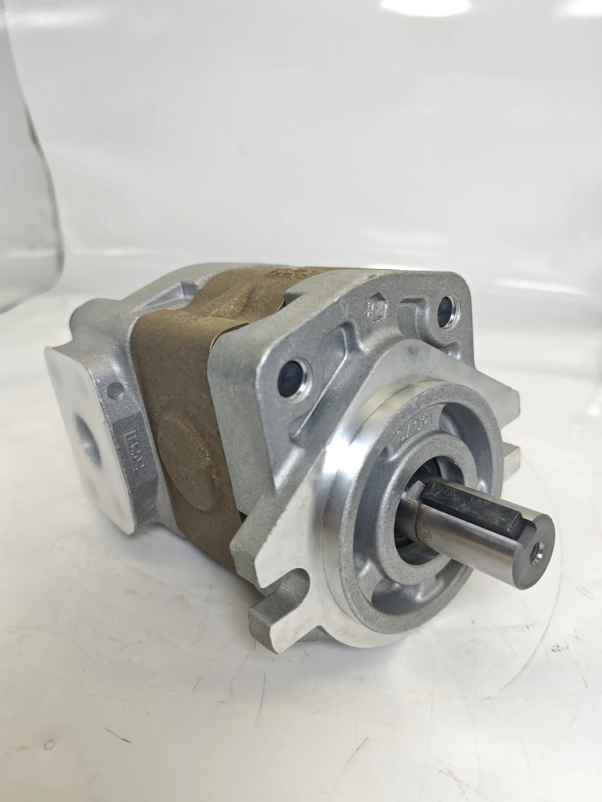

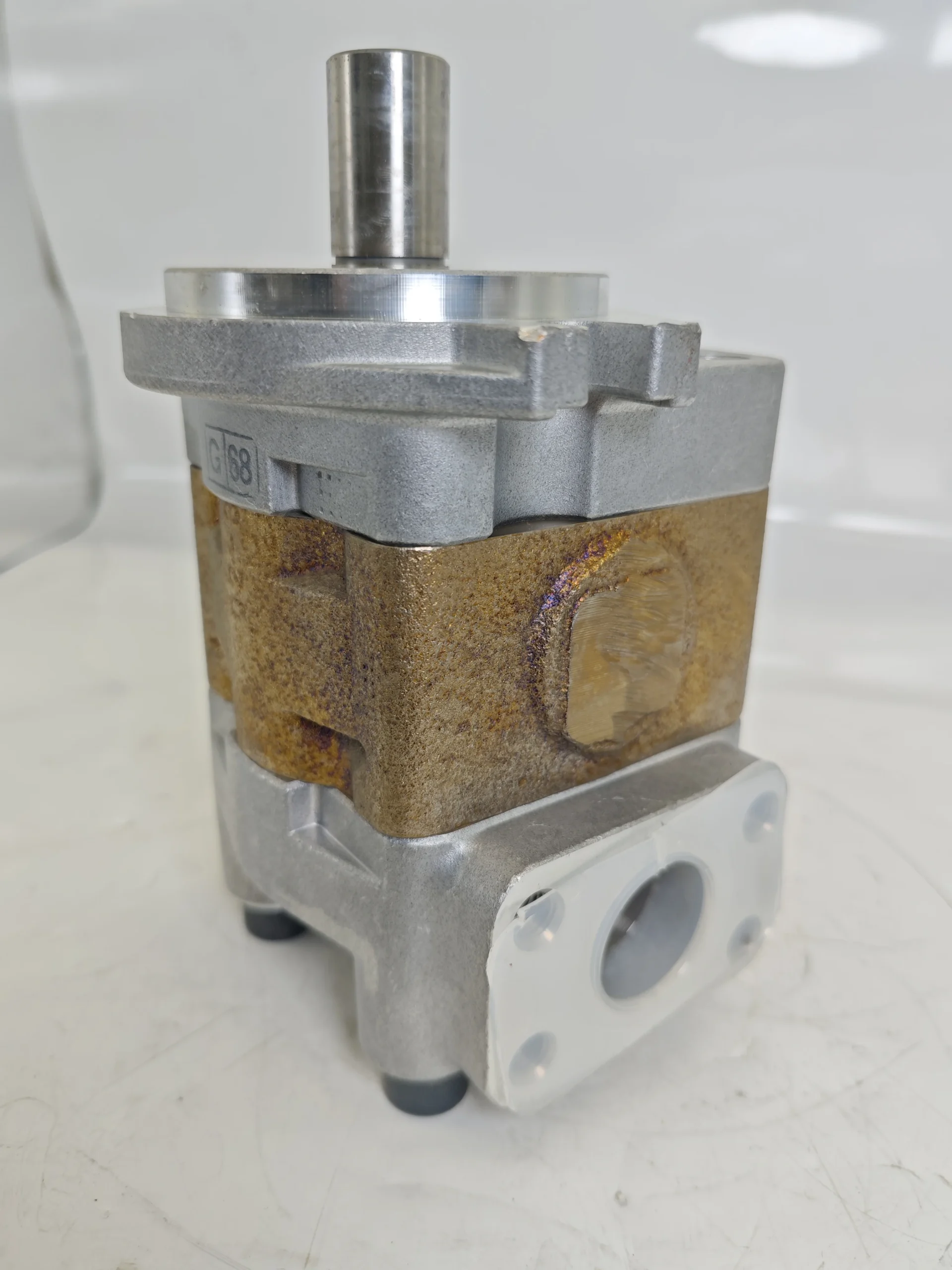
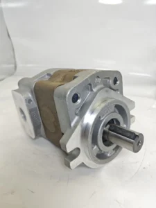
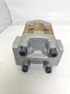

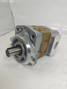

OEM SGP SGP2 SGP2A SGP1A Gear Hydraulic Pump SGP1A31 9D2H9-R005 Hydraulic External Triple Gear Pump for Forklift
1. Basic performance parameters- Pump body type: Single-stage external meshing quantitative gear pump, integrated with a micro relief valve, suitable for small hydraulic power systems, supporting unidirectional rotary oil supply
– Displacement and pressure parameters: Rated displacement 5 cc/rev (” R005 “in the model corresponds to the displacement specification); The rated working pressure is 160 bar, the maximum allowable pressure is 200 bar (short-term ≤5 seconds), and the return oil back pressure is ≤1.5 bar
– Speed and flow parameters: Rated speed 3000 rpm, maximum speed 4500 rpm (short time ≤3 minutes), minimum stable speed 500 rpm; The output flow rate at the rated speed is approximately 15 L/min (5 cc/rev×3000 rpm÷1000)
– Efficiency parameters: Rated working condition volumetric efficiency ≥92%, total efficiency ≥85%, pressure loss at rated flow ≤4 bar
2. Structure and connection parameters
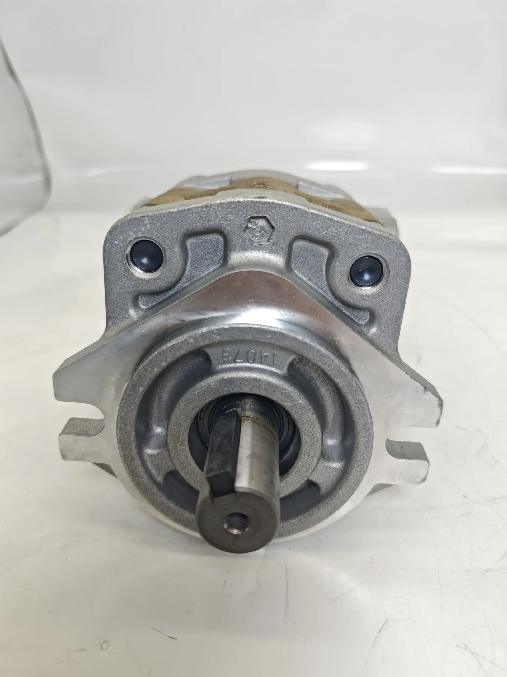
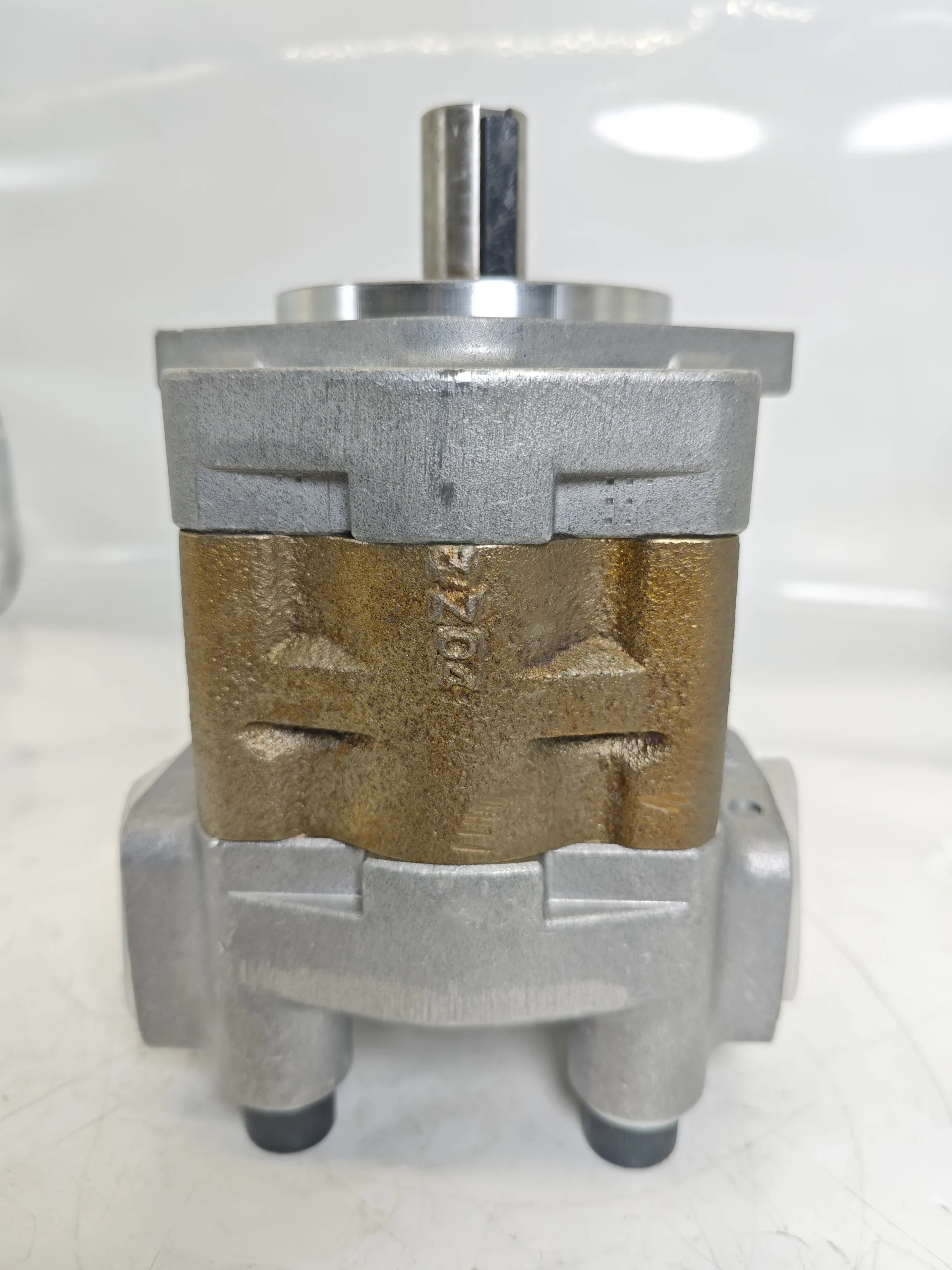
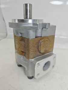
– Structural type: Aluminum alloy integral die-cast pump body, surface anodic oxidation treatment; Nitrided alloy steel gears (hardness HRC60-63), graphite-impregnated phenolic resin distribution plates, single-ended lip + mechanical combination seals
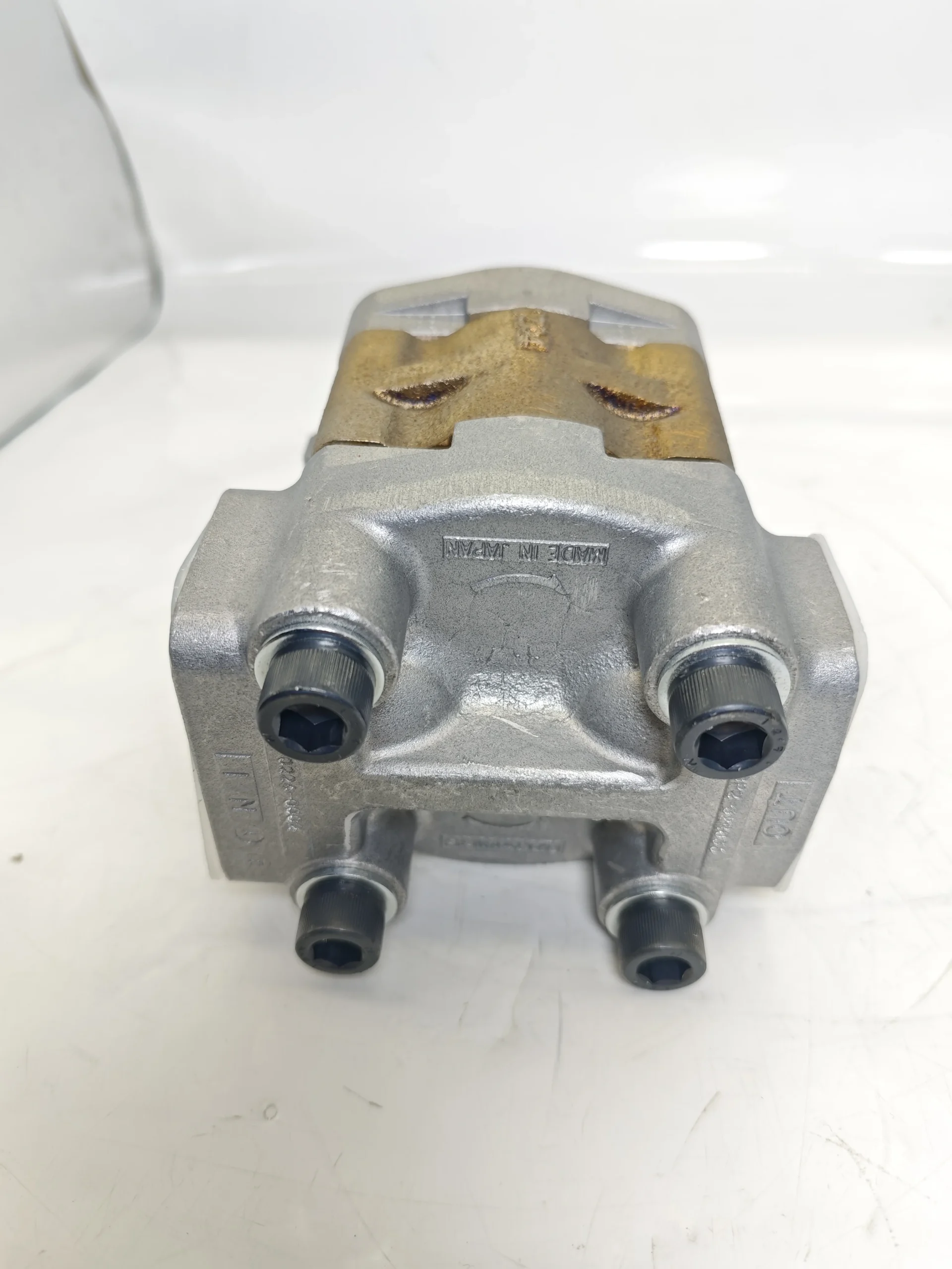
– Installation and connection specifications: Shaft end installation (compatible with ISO 9411 standard), and “9D2H9” in the model corresponds to the installation positioning dimensions; Oil port threads: Suction port G1/4, outlet port G1/4, control port G1/8; The output shaft is a knurled shaft or a micro flat key connection (specification: 4×10). The overall weight is approximately 1.2 kg, and the external dimensions (length × width × height) ≈100×80×65 mm
– Protection grade: IP64, suitable for compact installation Spaces of small equipment and general industrial environments
3. Medium and Environmental requirements
– Medium requirements: Compatible with L-HM 22/32/46 anti-wear hydraulic oil, allowable medium viscosity range 8-300 mm²/s, moisture content ≤0.03%, solid particle size ≤15 μm
– Environmental parameters: Operating environment temperature -20℃ to 80℃, relative humidity ≤95%; The cleanliness of the oil should reach ISO 4406 15/12 grade
– Filtration requirements: A filter screen of ≥100 mesh should be installed on the oil suction side, and the filtration accuracy on the oil return side should be ≤30 μm
Ii. Working Principle
This pump is a single-stage external meshing quantitative gear pump. Its core converts mechanical energy into hydraulic energy through the “periodic change of gear meshing volume”. The specific process is as follows:
1. Core mechanism of power transformation
The motor drives the driving gear to rotate, which in turn engages and rotates the driven gear in the opposite direction. A local vacuum is formed in the oil suction area where the two gears disengage. Under the action of atmospheric pressure, the hydraulic oil enters the pump chamber through the oil suction port and fills the gap between the gear tooth grooves. As the gears continue to rotate, the hydraulic oil in the tooth grooves is carried to the pressure oil zone on the meshing side. As the gears gradually mesh, the volume of the tooth grooves continuously decreases, and the oil is mechanically squeezed to generate pressure. The high-pressure oil under pressure is guided to the oil outlet through the distribution plate and discharged, then enters the small hydraulic system to drive the actuating elements (such as micro oil cylinders and small motors) to act.
2. Pressure protection mechanism
The integrated micro relief valve is connected in parallel between the oil outlet and the oil suction port. When the system pressure rises to the rated value of 160 bar, the valve core of the relief valve begins to open for unloading. When the pressure exceeds the maximum allowable value of 200 bar, the relief valve is fully open to guide the excess oil back to the suction chamber, preventing the pump body, pipelines and downstream components from being damaged due to overload. The graphite-impregnated distribution plate, through pressure self-lubrication and compensation design, reduces leakage between the gear end face and the distribution plate, maintaining high volumetric efficiency.
Iii. Product Features and Advantages
– Miniaturization and high integration: The volume of the aluminum alloy die-cast pump body is only 100×80× 65mm, and the weight is 1.2kg. Compared with the conventional gear pump of the same displacement, the volume is reduced by 30% and the weight is reduced by 40%. Integrated micro relief valve, no need for external pressure protection components, suitable for compact installation Spaces of small equipment
– High wear resistance and low loss: The gears undergo nitriding treatment to enhance surface hardness and are combined with self-lubricating distribution plates to reduce friction loss. The lip + mechanical combined seal design ensures a static leakage rate of ≤0.5 mL/min and a trouble-free operating life under rated conditions of ≥8000 hours
– Low-noise and energy-saving operation: By adopting a flanged tooth profile design to optimize the meshing process, the meshing clearance is controlled at 0.02- 0.04mm. The operating noise at a distance of 1 meter is ≤ 72dB, which is 3- 5dB lower than that of similar small pumps. High volumetric efficiency reduces energy loss and is suitable for small motor drive scenarios
– Wide adaptability and easy installation: A wide temperature range of -20℃ to 80℃ is suitable for different environments, and a rated pressure of 160 bar meets the requirements of medium and small loads. Supports direct installation at the shaft end and flange adapter installation. The oil port position can be adjusted as needed, adapting to the layout of various types of small equipment
Iv. Usage Functions and Purposes
1. Core usage functions
– Quantitative low-flow oil supply: Continuously provide stable pressure and flow of hydraulic oil for small hydraulic systems, serving as the power source for micro actuators, with an output flow accuracy of ±2%
– System pressure protection: The built-in relief valve precisely controls the maximum pressure, preventing small hydraulic components from being damaged due to overload and simplifying the system structure by replacing the external relief valve
– High-efficiency power transmission: Convert the mechanical energy of small motors into hydraulic energy to drive the extension and retraction of micro cylinders and the rotation of small motors, with a power transmission efficiency of ≥85%
2. Main uses
As a core power component of small hydraulic systems, it is suitable for small flow and medium and low pressure working conditions, connects micro motors with small actuating elements, and provides power for various light-load and precision small equipment. It is a key component of micro hydraulic transmission systems.
V. Applicable Machines and Scenarios
1. Adapt to the core machine
– Small industrial equipment: micro injection molding machines, small strapping machines, desktop CNC equipment, precision pneumatic/hydraulic fixtures
– Automated equipment: Small push mechanisms for automated production lines, electronic component assembly equipment, and small sorting robots
– Specialized small equipment: Medical rehabilitation devices (such as hydraulic-assisted prosthetic limbs), small agricultural machinery (garden pruning machines), small test bench hydraulic systems
– Vehicle assistance systems: Brake assist systems for small electric vehicles, small auxiliary action mechanisms for construction machinery (such as cab leveling for excavators)
2. Typical application scenarios
– Precision fixture drive scenario: When equipped with a micro hydraulic fixture for CNC lathes at a rated pressure of 160 bar and a flow rate of 15 L/min, the drive fixture cylinder can complete the clamping action within 0.5 seconds, with a stable clamping force error of no more than 1%, meeting the requirements for clamping accuracy in precision processing
– Small strapping machine scenario: Drive the paper pressing mechanism of the small carton strapping machine. At a rated speed of 3000 rpm, the stroke of the paper pressing cylinder is 50 mm, the action cycle is 1.2 seconds, and it can work continuously for 8 hours without pressure attenuation, meeting the efficiency requirements of the assembly line strapping
– Medical rehabilitation equipment scenario: As a hydraulic-assisted joint drive source for prosthetic limbs, the low-noise (≤ 72dB) design enhances the user experience. The wide temperature range of -20℃ to 80℃ is suitable for different environments, and the compact structure makes it easy to integrate into the interior of the prosthetic limb shell
Six. Similar models
1. Different models of the same series displacement
-SGP1A31 9D2H9-R003: Rated displacement 3 cc/rev, rated flow 9 L/min, rated pressure 160 bar. It is suitable for ultra-small hydraulic systems (such as micro test benches, precision electronic equipment), with a more compact size and a weight of only 0.8 kg
-SGP1A31 9D2H9-R008: Rated displacement 8 cc/rev, rated flow 24 L/min, maximum pressure 180 bar, suitable for medium and small-sized equipment (such as small hydraulic lifting platforms, medium-sized baling machines), with stronger power
2. Models with the same displacement but different functions
-SGP1A31 9D2H9-R005-M: Model without integrated relief valve, requires external pressure control components, suitable for customized pressure regulation scenarios, with a 15% lower cost
-SGP1A319D2H9-R005-E: Model with pressure sensor interface, supporting real-time monitoring of oil outlet pressure, suitable for precision control scenarios that require pressure feedback (such as medical equipment), with a 30% higher cost
-SGP1A31 9D2H9-R005-F: A Flanged installation model, suitable for equipment that requires fixed installation, with enhanced installation stability. Other performances remain the same as the original model
SGP1
SGP2
GPY
YP10
YP15
YPD1
YPD2
SYD1
SYD2
SYD3
SYD4
SD
SDY
D1
D2
D3
D4
D5
YPD1-2.52.5A2D2-L038
SGP1A16R
SGP1A18R
SGP1A20R
SGP1A23R
SGP1A25R
SGP1A27R
SGP1A30R
SGP1A32R
SGP1A34R
YPD1-2.52.5A2D2-L
YP15-14A2H2-R304
GPY-11.5R
GPY-3R
GPY-5.8R
GPY-7R
GPY-9R
GPY-8R
GPY-4R
STYB-27.27.16L846
GPY-10R
YPD1-2.5-2.5A2D2-L644
YP10-3.5A2D2-R417
YP10-3.5R
SGP1A23F1H2R
SGP1A23L988
SC60S-112
YP10-2.5A2H2-L421
YP10-2.5A2D2-L407
SC125S-112
Installation and commissioningWhen installing, ensure that the coaxiality error between the pump shaft and the motor shaft is ≤ 0.08mm. Use a flexible coupling for connection. It is strictly prohibited to directly apply radial force to the pump shaft to avoid gear meshing jamming
The oil suction pipeline should be short and thick (length ≤1 meter, diameter ≥10 mm), and the distance between the oil suction port and the bottom of the oil tank should be ≥50 mm to avoid excessive oil suction resistance causing cavitation. The pipeline connection adopts oil-resistant sealing gaskets to ensure a tight seal without air leakage
Before the first start-up, a small amount of hydraulic oil (about 5 mL) should be injected into the pump cavity, and the motor shaft should be manually rotated 3 to 5 times to ensure there is no jamming. When starting up, first open the oil suction valve and run it no-load at low pressure (30 bar) and low speed (1500 rpm) for 15 minutes, gradually increasing it to the rated parameters
When installed in a compact space, it is necessary to ensure that there is a heat dissipation space of ≥ 50mm around the pump body. When the ambient temperature exceeds 40℃, ventilation and heat dissipation should be enhanced to prevent the oil temperature from being too high and accelerating the aging of the sealing parts
2. Operation and Maintenance
During operation, the pump body temperature (normal ≤75℃, maximum not exceeding 85℃), outlet pressure and noise should be monitored weekly. If the temperature rises sharply by more than 10℃, the pressure fluctuates by more than 3 bar or abnormal noises occur, stop the machine immediately for inspection. Focus on checking the cleanliness of the oil (once every two months), gear wear or seal leakage
– Regular maintenance cycle: Replace the hydraulic oil and filter element every 3,000 hours; Disassemble and inspect the gear wear every 6,000 hours (replace when the tooth surface wear is ≥ 0.05mm), and replace the sealing parts. The pressure setting value of the relief valve should be calibrated with a pressure gauge every 1500 hours
– Do not run without oil (idling for more than 3 seconds may cause gear damage). Do not operate for a long time at the maximum speed (no more than 5 minutes at a time). Before the system is shut down, it should first be reduced to low pressure and run no-load for 3 minutes. When the oil temperature is ≤50℃, the oil source should be cut off
3. Storage and Protection
When stored for a long time, use a dedicated plug to seal the oil port, inject a small amount of anti-rust oil (about 2 mL) into the pump cavity, and apply a thin layer of lithium-based grease to the pump shaft. Store in a dry warehouse with a temperature ranging from 0 to 40℃ and a humidity of no more than 60%. Avoid direct sunlight and oil contamination. Manually rotate the pump shaft once every two months
Before putting the pump into use after being idle for more than six months, the pump cavity should be flushed with clean hydraulic oil and the sealing parts replaced. Run the low-speed no-load test for 10 minutes to check the pressure stability and leakage rate (≤0.5 mL/min is normal). Only after meeting the standards can it be connected to the system


