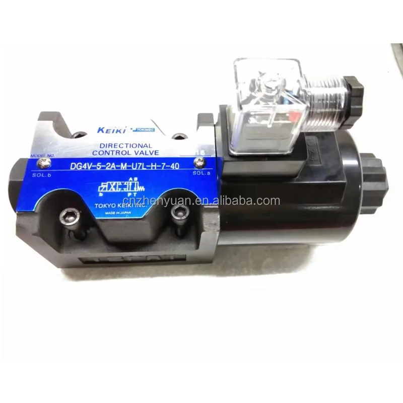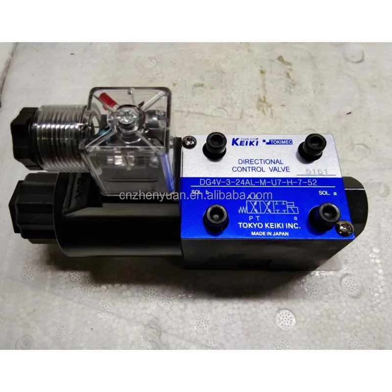

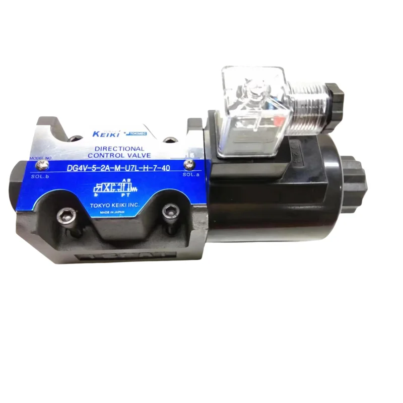
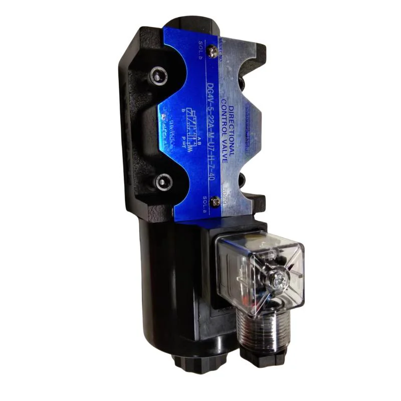
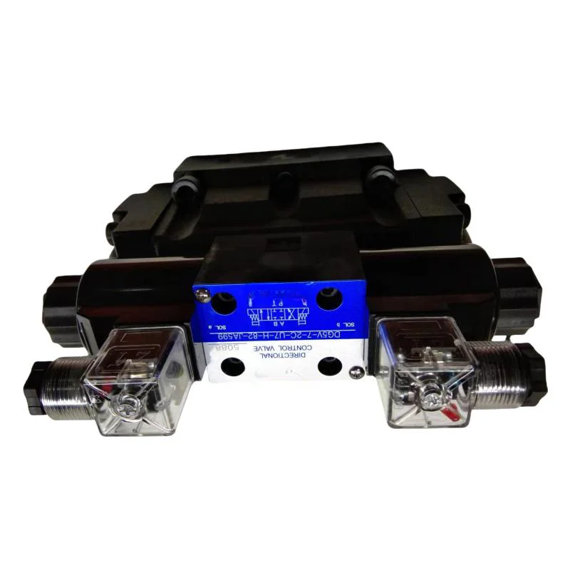
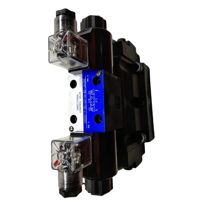
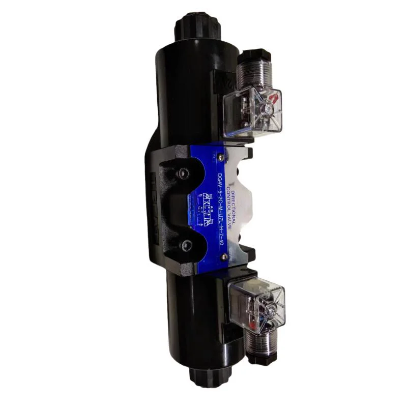
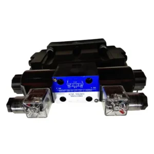
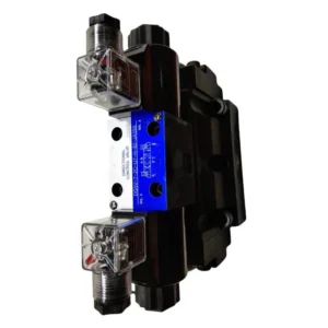
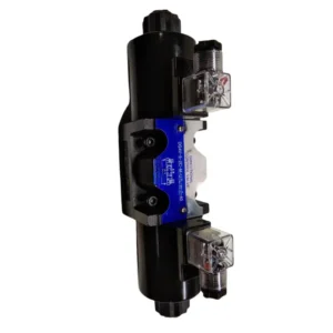
The high-performance DG3V, DG4V, and DG5V series solenoid and hydraulically operated directional control valves manufactured by LIC Hydraulic (featuring industry-benchmark models such as DG4V-3-2C-U-H-100 and DG4V-3-6C-U-H-100) are precision-engineered fluid control components designed to direct, start, stop, and regulate fluid flow vectors. Fully conforming to international ISO 4401-03, Cetop 3, and NFPA D03 standard subplate patterns, this line delivers 100% drop-in interchangeability with original Tokyo Keiki (formerly Tokimec) directional valves.
Engineered to fulfill the rigid uptime expectations of automated production machinery and high-duty injection molding networks, LIC’s valves overcome the performance shortfalls of standard aftermarket hardware, which is often prone to thermal fatigue and internal spool binding. Every DG4V assembly undergoes 100% full-load simulated high-frequency operation factory testing prior to shipment. Even when driven continuously at a maximum system pressure of 350 bar with maximum volumetric flow, our valves maintain superior shift reliability and low internal slippage, standing as an optimal global B2B procurement choice.
Technical Specifications
Accurate engineering profile based on standard manufacturer parameters for Tokyo Keiki DG4V-3 series valves:
Model: DG4V-3-2C-U-H-100 (Standard Center Closed Function)
Nominal Size / Interface: NG6 / Cetop 3 / ISO 4401-03 subplate footprint
Spool Type Configuration: 2C (3-position, 4-way; Spring centered, all ports P, A, B, T blocked in neutral position)
Maximum Pressure at Ports P/A/B: 350 bar (35 MPa)
Maximum Allowable Tank Port Backpressure: 210 bar (21 MPa)
Maximum Flow Capacity: Up to 80 L/min (Depending on individual spool routing and circuit delta-P)
Solenoid Power Designation: U (High-performance AC/DC wet-armature solenoid configuration with DIN 43650 plug orientation)
Design Sequence: 100 series (Signifying upgraded flow path dynamics and high-efficiency coils)
Model: DG4V-3-6C-U-H-100 (Standard Center Release Function)
Nominal Size / Interface: NG6 / Cetop 3 / ISO 4401-03 subplate footprint
Spool Type Configuration: 6C (3-position, 4-way; Spring centered, port P blocked, working ports A and B cross-connected to tank T in neutral)
Maximum Pressure at Ports P/A/B: 350 bar (35 MPa)
Maximum Allowable Tank Port Backpressure: 210 bar (21 MPa)
Maximum Flow Capacity: Up to 60 L/min
Mounting Format: Subplate / Manifold block mounting configuration
Key Technical Advantages
Optimized Cast Iron Low-Loss Internal Geometry: The main valve housings are cast from high-density, high-tensile industrial cast iron utilizing core-molding techniques that produce smooth internal boundaries. This reduces fluid resistance and internal pressure drops ($\Delta P$) when hydraulic fluid flows at high velocities, minimizing heat generation during intensive, high-frequency control cycles.
Wet-Armature Solenoid with Enhanced Thermal Resilience: Features a wet-pin solenoid architecture where the internal moving armature operates fully immersed in hydraulic oil. This provides self-lubrication across the stroke and cushions internal mechanical impact, leading to quiet operation. The high-response coils exhibit short cycle times (switching within 20-30 ms) and prevent insulation breakdown or thermal burnout.
Micro-Finished Spool with Anti-Lock Equalization Grooves: The directional control spools are ground and lapped to micron-level clearances from premium hardened bearing steel stock. A series of precision circumferential pressure-equalization grooves are machined into the land surfaces to neutralize lateral hydraulic imbalance forces, preventing “hydraulic lockup” under full continuous 350 bar pressures.
High-Backpressure Tolerant Tank Chamber Construction: By reinforcing the walls of the T-port cavity and upgrading the dynamic end seals, this valve line safely sustains static or transient tank line backpressures up to 210 bar. The outer shaft seals remain secure and bubble-tight even when valves are arranged in series or exposed to return-line pressure spikes.
Application Areas
The DG4V-3 directional valve family delivers high operational reliability and exceptional lifecycle metrics, making it an ideal choice for complex automated manifolds:
CNC Machine Tools & Machining Centers: Providing dependable direction control for high-repetition clamping cylinders, tool changers, and counter-balance cylinders.
Plastics & Injection Molding Machinery: Deployed as high-speed pilot stages for large logic elements or as primary directional actuators for core-pulling and ejection units.
Primary Metallurgy & Steel Mill Processing Lines: Regulating raw material feeders, coil handlers, and automated heavy-duty sub-assemblies within hydraulic power stations.
Woodworking, Pulp, & Paper Machinery: Installed on multi-station manifold blocks requiring non-stop direction control under high ambient humidity and temperature variables.
Expert Maintenance Tips
Prevent Spool Distortion via Uniform Torquing: Given the tight tolerances of the NG6/Cetop 3 housing, the surface flatness deviation of the mounting manifold must not exceed 0.01 mm over its length. Tighten the four mounting bolts using a calibrated torque wrench in a crosswise pattern to a recommended torque of 5-7 Nm. Uneven or excessive torque will distort the bore geometry, causing the spool to bind.
Manage Voltage Tolerances and Plug Integrity: Solenoid coils dissipate heat during extended actuation cycles; verify that the DIN connector gaskets are fully seated. For environments with water spray or cutting fluids, maintain a solid moisture barrier. Ensure supply voltage fluctuations are kept within $\pm 10\%$ of nominal parameters to mitigate excessive inductive heating caused by incomplete armature shifts.
Enforce Fluid Cleanness to Counteract Gumming: The accumulation of fine particulate matter or varnishes stemming from thermal oil degradation can lead to sticky operation within the tight tolerances of the spool assembly. Keep the system fluid cleanliness levels governed to ISO 4406 20/18/15 or better, and check internal pilot screens periodically to halt debris migration.
Related Models:
DG4V-5-3C-M-PL-T-6-40-P10
DG4V-5-6C-M-PL-D-6-40
DG4V-5-6C-M-U1-H-7-40
DG4V-5-6C-M-P7L-T-7-40
DG4V-5-6C-M-PL-0V-7-40
DG4V-5-0A-M-P7L-H-7-40
DG4V-5-0A-M-PL-T-6-40
DG4V-5-0A-M-PL-OV-6-40
DG4V-5-2A-M-PL-T-6-40
DG4V-5-2A-M-PL-OV-6-40
DG4V-5-2A-M-PL-D-6-40
DG4V-5-2A-M-P7L-H-7-40-JA1Y
DG4V-5-22A-M-PL-T-6-40
DG4V-5-23A-M-PL-T-6-40
DG4V-5-0B-M-P7L-H-7-40-JA1Y
DG4V-5-2BL-M-P7L-H-7-40-JA1Y
DG4V-5-6B-M-P7L-H-7-40
DG4V-5-2C-M-P7L-H-7-40
DG4V-5-2C-M-PL-T-6-40-P10
DG4V-5-2C-M-PL-OV-6-40
DG4V-5-3C-M-PL-T-6-40-P15
DG4V-5-3C-M-P7L-H-7-40-JA415Y
DG4V-5-6C-M-P7L-H-7-40
DG4V-5-6C-M-PL-OV-6-40
DG4V-5-7C-M-PL-T-6-40
DG4V-5-7C-M-P7L-H-7-40-JA487Y
DG4V-5-33C-M-PL-T-6-40
DG4V-5-33C-M-P7L-H-7-40-JA569Y
DG4V-5-2N-M-PL-OV-6-40-P30