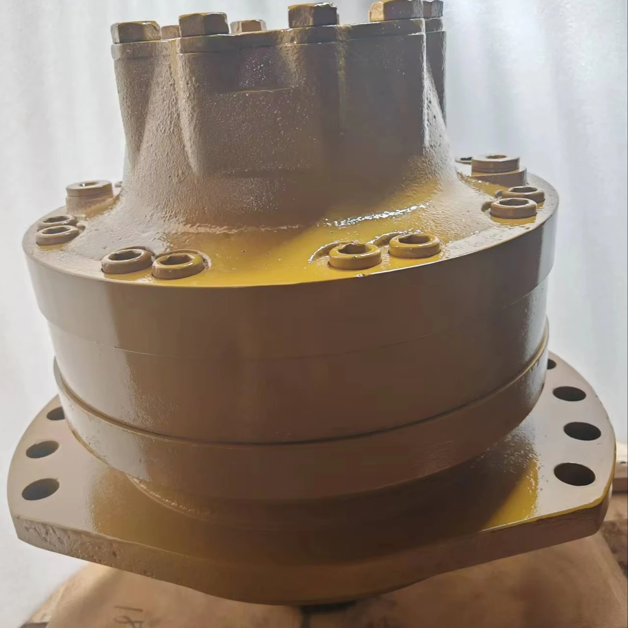
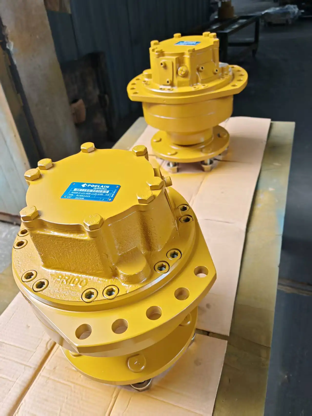
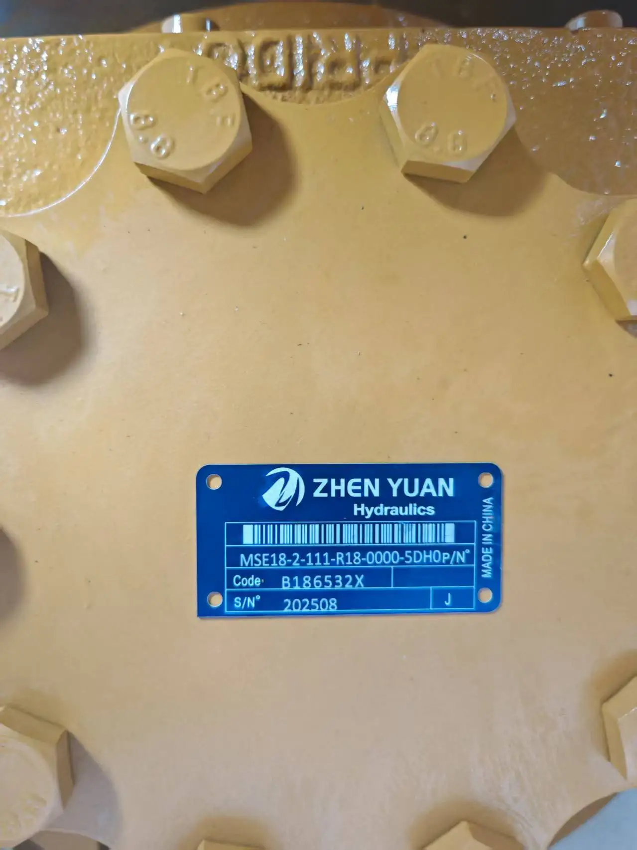
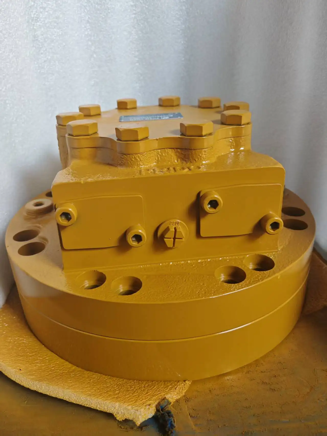
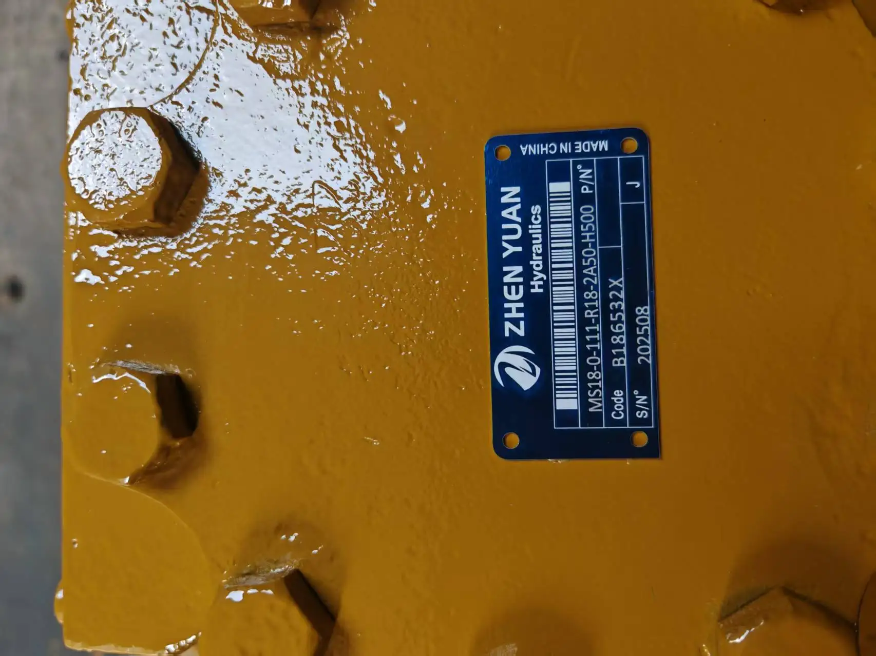
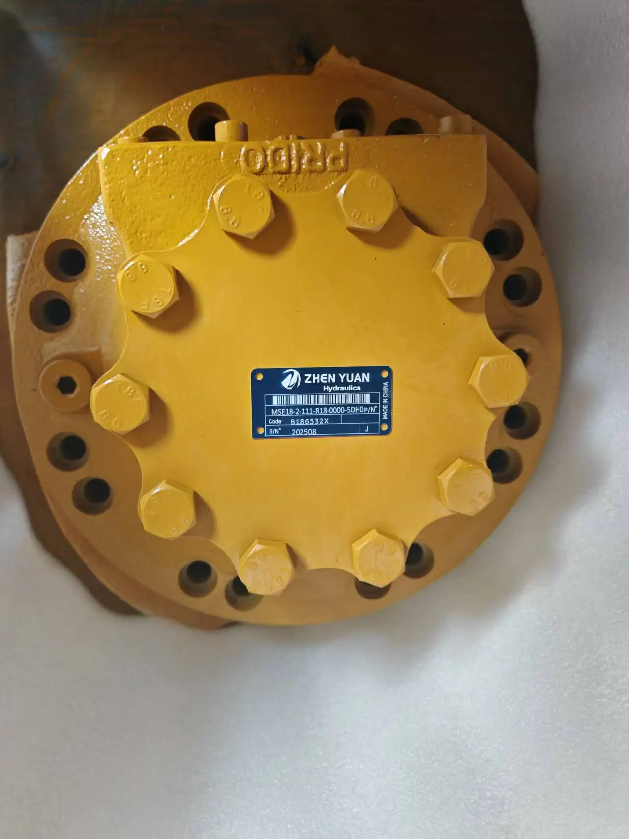

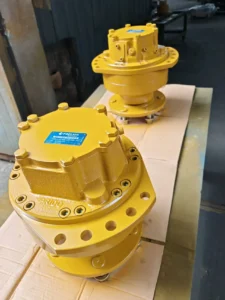
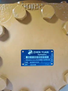


Wheel Hydraulic Motor MS MSE 02 05 08 11 25 35 50 83 Series MSE18-2-111-R18-0000-5DH0 Low Speed High Torque Piston Motor
Basic specifications
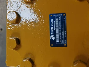
Type: Inner curve multi-acting radial piston hydraulic motor, specially designed for wheel drive, MSE18 series, 2 indicates specification level, 111 is the displacement code, R18 is the rotation direction code, 0000 is the output shaft type, 5DH0 is the special function configuration
Nominal displacement: approximately 1747ml/r (standard displacement of MS18-2 series), and about 262L/min when the theoretical flow rate is 150r/min
Rated working pressure: 25MPa (250bar), short-term peak pressure up to 40MPa (400bar), suitable for medium and high-pressure heavy-load working conditions
Rated speed: 278r/min, short-term maximum speed can reach 500r/min, minimum stable speed ≤0.5r/min, it belongs to low-speed high-torque type motor
Output torque: approximately 6528N · m (at 25MPa pressure), maximum peak torque approximately 8500N · m (short time)
Output power: approximately 190kW (under rated conditions), maximum up to 240kW (for short periods)
Rotation direction: Standard clockwise (viewed from the shaft end), R18 indicates the standard rotation direction
Weight: Approximately 380kg (excluding accessories), compact structure, high power density
Working parameters
Volumetric efficiency: ≥92% (under rated conditions), with low energy conversion loss
Overall efficiency: ≥85%, with highly efficient comprehensive performance
Applicable medium: Anti-wear hydraulic oil (viscosity index ≥90), L-HM46 or L-HV46 hydraulic oil is recommended, which is particularly suitable for emulsion medium environments
Medium viscosity: 10-300mm²/s, optimal working viscosity: 20-60mm²/s
Medium temperature: -20℃ to +85℃, recommended working temperature: 30-55℃
Oil cleanliness: ISO 4406 18/15 grade. A 10μm precision filter must be installed to protect the precision componentsIi. Working Principle
The core working mechanism of the inner curve radial piston motor:
Structural features
It adopts an inner curve multi-acting radial plunger structure. The inner wall of the stator (CAM ring) has multiple evenly distributed special curved surfaces (usually 5 to 8 segments).
Multiple plunger holes are evenly distributed radially on the rotor, and each hole is equipped with a plunger and roller assembly
The distribution shaft is fixed and connected to the inlet and return oil ports, responsible for distributing high-pressure oil and low-pressure oil
The output shaft is rigidly connected to the rotor and bears the working torque
The wheel flange is directly integrated onto the output shaft and can be directly connected to the wheel hub, eliminating the need for intermediate transmission links
Principle of torque generation
High-pressure oil enters the distribution shaft from the oil inlet and then passes through the distribution window into the bottom of the plunger in the oil inlet working section
The oil pressure drives the plunger to move outward, and the rollers at the head of the plunger closely adhere to the inner surface of the stator
Due to the special curve on the inner surface of the stator, the extension length of the plunger at different positions varies, and the radial force generated is also different
The stator curve enables the plunger to complete multiple reciprocating motions within each revolution of the rotor (the number of actions is equal to the number of stator surface segments).
The radial force of the plunger is converted into a tangential force on the rotor through the rollers, thereby generating torque to drive the output shaft to rotate
Multiple plungers work in rotation to output continuous and stable torque, with torque fluctuations controlled within ±3%
Oil flow direction
High-pressure oil → Oil inlet → high-pressure window of the distribution shaft → Oil chamber at the bottom of the plunger → Push the plunger to move outward
The plunger moves → drives the rotor to rotate → the output shaft acquires torque → drives the wheels
The plunger reaches the oil discharge working section → the oil → the low-pressure window of the distribution shaft → the oil outlet → returns to the oil tank
The distribution shaft rotates synchronously with the output shaft to ensure that each plunger is connected to the high and low pressure oil in the correct position
Rotation direction control
By switching the direction of the oil inlet and return ports, the direction of the hydraulic pressure acting on the plunger is changed
The change in the direction of the hydraulic pressure causes the tangential component force to reverse, achieving the forward and reverse rotation function of the motor
The MSE18 series can be easily rotated in both directions through a directional control valve, meeting the requirements for vehicle forward and backward movement
Iii. Product Features and Advantages
1. Outstanding low-speed high-torque performance
Ultra-high starting torque: The starting torque efficiency is ≥92%, allowing for direct start under load without the need for acceleration without load. It is suitable for vehicle starting and climbing slopes
Low-speed stability: It can operate smoothly without crawling at an ultra-low speed of 0.5r/min, making it suitable for precise control and fine-tuning
High torque output: Under the same volume, the output torque is 5 to 8 times that of a gear motor, making it suitable for driving heavy-duty vehicles
Small torque ripple: The uniform distribution of multiple plungers and the internal curve design keep the torque fluctuation within ±3%, making the vehicle run more smoothly
2. Structural and reliability advantages
Force balance: The radial plungers are symmetrically distributed, which makes the radial forces cancel each other out, reduces the bearing load, and extends the service life
Impact resistance: It can withstand an instantaneous impact of 200% of the rated pressure and adapt to changes in road conditions and bumps
Reliable sealing: Made of special wear-resistant sealing materials, it is resistant to high temperatures and oil, has low leakage and a long service life
Strong durability: The key friction pairs are treated with special heat treatment processes, and the average mean time between failures exceeds 10,000 hours
Integrated design: The motor and wheel flange are integrated, reducing transmission components and enhancing system reliability
3. System adaptability and control characteristics
Bidirectional rotation: The forward and reverse rotation can be easily achieved through the directional control valve, adapting to the vehicle’s forward and backward movement and simplifying the design of the hydraulic system
Good self-priming ability: No additional auxiliary pump is required, and the suction lift can reach 4 meters (depending on the viscosity of the medium)
Modular design: Brakes, dual-speed functions, special seals, etc. can be selected as needed to enhance system integration
Multiple installation methods: We offer a variety of flange and shaft extension forms to adapt to different wheel hub interfaces
It can withstand radial and axial loads: It adopts a tapered roller bearing structure and directly drives the wheels without additional support
4. Maintenance and Economy
Easy maintenance: Modular structure, main components can be replaced separately, reducing maintenance time by 50%
Long service life: Special materials and heat treatment processes ensure that the key friction pairs have a service life of over 15,000 hours
Energy consumption optimization: Maintain high efficiency under light load conditions and reduce vehicle operating costs
Wide adaptability: It can operate within a temperature range of -20 ℃ to +85℃ and adapt to various environmental conditions
Emulsion adaptability: The unique emulsion compatibility of the MSE series makes it suitable for special industries such as coal mines
Iv. Usage Functions and Purposes
Core functions
Convert the pressure energy of the hydraulic system into mechanical energy to provide direct wheel driving force for the vehicle
Precisely control the output torque and rotational speed to meet the requirements of different road conditions and loads
In coordination with the hydraulic control system, it realizes functions such as the vehicle’s forward movement, reverse movement, and steering
Main application fields
Walking system for construction machinery
Chassis walking drive for large excavators, bulldozers, loaders, etc., providing strong traction and climbing ability (with a maximum climbing Angle of up to 30°)
Roller drive wheels ensure uniform and smooth road surface construction
It provides smooth transitions when switching between high and low speeds and turning, reducing shock
Mine transport vehicles
Wheel-side drive for mining trucks and underground transport vehicles, suitable for harsh road conditions and heavy loads
Provide reliable power in damp and dusty environments and reduce maintenance frequency
The MSE series is particularly suitable for use in underground coal mines and has good adaptability to emulsion media
Port and logistics equipment
The wheel drive of container forklifts and straddle carriers provides high torque and precise control
Maintain stable output under frequent start-stop and heavy load conditions to improve operation efficiency
Special vehicles
The traveling systems of crawler cranes and off-road vehicles provide strong traction
The drive systems of special vehicles such as fire engines and rescue vehicles are suitable for complex terrains
Industrial application
Roller drive for metallurgical equipment, suitable for high-temperature environments
Large conveyor belt drive, providing stable power in harsh environments
V. Applicable Machines and Scenarios
1. Typical applicable machines
Large excavator walking system
It is particularly suitable for large excavators of 30 to 50 tons, such as the PC400 and ZX470 models of a certain brand
As a walking motor, it provides strong traction and climbing ability, and can offer stable power output even in muddy, rough and other harsh terrains
When performing compound actions, it coordinates and cooperates with the working device to increase the overall efficiency of the machine by 15-20%
Large mining trucks
It is applicable to mining dump trucks of 100 to 300 tons
Provide stable driving force under heavy load conditions to ensure the efficiency of road transportation in mining areas
In conjunction with the hydraulic braking system, it achieves safe and reliable vehicle control
Maintain reliable operation in the harsh environment of the mining area (dust, humidity) and reduce maintenance downtime
Large roller
It is suitable for vibratory rollers of 30 to 50 tons
As a drive motor, it provides powerful driving force to ensure the compaction effect
Maintain a stable speed under different working conditions to improve construction efficiency and quality
In coordination with the vibration system, it achieves efficient compaction of the road surface
2. Characteristics of applicable scenarios
Low-speed and heavy-load working conditions that require extremely large torque output, such as mining vehicles and large construction machinery
Precision control equipment that requires smooth operation and low noise, such as precision processing machinery and large injection molding machines
It can adapt to high-temperature, humid, dusty and salt spray environments in harsh working conditions such as mines, metallurgy and ports
The working device of construction machinery that requires frequent start-stop and reversing responds quickly and has little impact
In high-pressure application scenarios where the hydraulic system pressure is stabilized at 20-35 mpa, its high-pressure performance advantages are fully exerted
It is particularly suitable for special working environments such as underground coal mines with emulsion media
Six. Similar models
1. Different specifications and models of the same series
MSE18-1: Displacement approximately 191 mL /r, output torque about 6,840 N · m, power around 70kW, suitable for larger construction machinery and Marine equipment
MSE18-2: Of the same specification and level as this model, with a displacement of approximately 1747ml/r, an output torque of about 6528N · m, and a power of approximately 190kW, the basic parameters are the same
MSE18-0: With a slightly smaller displacement, the output torque is correspondingly reduced, making it suitable for medium-sized construction machinery
2. Different series models of the same type
MSE11 series: With a relatively small displacement range (1000-1500 mL /r), the output torque is approximately 4000-6000N · m, making it suitable for medium-sized construction machinery and agricultural machinery
MSE25 series: It has a wider displacement range (2500-3500ml/r) and an output torque of up to 8000-12000N · m, making it suitable for super heavy construction machinery and mining equipment
MS18 series: It has the same basic structure as MSE18, but the MS series is suitable for mineral oil media, while the MSE series is suitable for emulsion media and has better anti-emulsification performance
3. Domestic alternative products
YMD series: Domestic internal curve radial piston motor, similar in performance to the MSE18 series, more economical in price, suitable for maintenance and matching in the domestic market
HNM series: Domestic low-speed high-torque hydraulic motors, with displacement ranges and performance parameters close to those of the MSE18 series, can be used as substitutes under certain conditions
JMDG series: Domestic radial piston motors, with parameters similar to the MSE18 series, have a significant price advantage and are suitable for application scenarios with limited budgets
Vii. Precautions for Use
1. Installation points
Direction confirmation
It must be installed in the specified direction (standard clockwise). The oil inlet and return ports must not be connected in reverse; otherwise, the internal seal and distribution mechanism will be damaged
The oil inlet is connected to the system pressure oil, the oil outlet is connected to the oil tank, and the oil drain is separately led back to the oil tank and not connected to the back pressure
Fixation and connection
The installation plane must be flat (flatness < 0.1mm), and the fixing bolts should be evenly tightened (torque should meet the specified requirements) to prevent the shell from deforming and affecting the movement of the plunger
The output shaft and the wheel hub must be connected by an elastic coupling. Rigid connection is strictly prohibited
Coaxiality error is less than 0.05mm, angular deviation is less than 0.5°, reducing vibration and bearing load
The installation bracket must have sufficient rigidity to prevent vibration and displacement during operation
Pipeline configuration
The diameter of the oil inlet pipe should be no less than 80mm and the length less than 2m to reduce the oil suction resistance and prevent cavitation
The diameter of the oil outlet pipe should be ≥65mm to ensure smooth oil return and a back pressure of less than 0.5MPa
The oil drain pipe must be led back to the oil tank separately and not connected to back pressure to ensure the smooth discharge of the leaked oil inside
All pipelines must be firmly fixed to prevent vibration and wear
2. Startup and Operation management
Startup program
Check the oil level in the fuel tank (≥ 500mm above the suction port) and the oil temperature (≥-10℃)
Manually turn the wheel 2 to 3 times to ensure there is no jamming
Loosen the exhaust plug, jog the start motor to exhaust, and then tighten it after continuous oil output
Start the machine without load and run it for 10 to 15 minutes to observe if there are any abnormal noises or leaks
Gradually load (each time ≤25% of the rated pressure, with an interval of ≥3 minutes). It is strictly prohibited to directly load the cold machine to full capacity
Operation monitoring
Oil temperature: Normal operating temperature is 30-55℃. If the temperature exceeds 70℃, the machine should be shut down to check the cooling system
Pressure: Not exceeding the rated value (25MPa), peak not exceeding 40MPa and cumulative time less than 10 minutes per hour
Noise: Smooth operation <85dB. Abnormal noise (>90dB) indicates possible wear or cavitation, and the machine should be stopped immediately
Leakage: Slight seepage (<15 drops per minute) is allowed. If the leakage increases, timely maintenance is required
Wheel operation: Observe whether the wheel operation is smooth, and whether there is any abnormal vibration or wobbling
3. Maintenance and care
Daily inspection
Check the oil level, temperature, noise and leakage conditions every shift, and record the operating parameters
Check if the connecting bolts are loose and tighten them in time
Clean the surface of the motor to prevent the accumulation of oil stains from affecting heat dissipation
Check the pressure difference of the filter to ensure the filtration effect
Regular maintenance
Every 250 hours: Check the pressure difference of the filter (<0.15MPa), and replace the filter element if necessary
Every 500 hours: Check the contamination level of the oil (≤ISO 4406 18/15 grade), and take samples for testing if necessary
Every 1000 hours: Change the hydraulic oil and clean the oil tank and filter at the same time
Every 2000 hours: Comprehensive disassembly and inspection, measurement of key fit clearances, and replacement of worn parts (such as plungers and rollers)
Oil Product management
Hydraulic oils of different brands must not be mixed to prevent the reaction of additives and the formation of sediment
In cold regions, low-viscosity hydraulic oil (such as L-HV series) should be used to ensure low-temperature starting performance
Regularly test the viscosity and acid value of the oil to ensure they meet the usage requirements
The cleanliness of hydraulic oil is of vital importance, and filters must be inspected and replaced regularly
4. Special Precautions
Prevent dry running
It is strictly prohibited to start the motor without oil. Even a short period of dry running will cause severe wear on the plunger and stator
After a long period of inactivity, when restarting the motor, clean hydraulic oil should be filled into it
Before starting, it is necessary to confirm that the fuel supply system is working properly
Prevent cavitation
Ensure that the oil suction pipeline is well sealed to prevent air from entering the system and forming bubbles
The oil suction height should be less than 500mm, and it is recommended to be less than 300mm to reduce the oil suction resistance
When the oil temperature is too low (<10℃), run it no-load for 20 minutes first to increase the oil temperature before loading
Load matching
It is strictly prohibited to operate beyond the rated pressure and speed; otherwise, the service life will be significantly shortened
Avoid frequent overload impacts and protect the precision mating parts inside the motor
Theoretically, it is not allowed for the maximum torque and the highest rotational speed to occur simultaneously to avoid overload
When climbing a slope, sudden acceleration or deceleration should be avoided to prevent sudden changes in torque
Shutdown protection
Before shutting down, the oil should be unloaded to a low pressure (<20bar) and run for 5 to 10 minutes. Only when the oil temperature drops below 60℃ should the power be cut off
When the motor is not in use for a long time, the oil inlet and outlet ports should be sealed to prevent foreign objects from entering the interior
When the equipment is out of use for a long time in winter, anti-freezing measures should be considered to prevent the internal moisture from freezing and damaging the parts
MS05-0-113-F05-1K29-EJ00 MS05-0-D24-F05-1620-EM00、 MS05-0-G24-F05-1620-EM00、 MS05-0-D24-F05-1620-EM00 MS05-0-G24-F05-1620-EM00、
MS05-0-D24-R05-1620-EM00、 MS05-0-G24-R05-1620-EM00 MS05-1-113-R05-2A50-E000、 MSE05-2-113-R05-2A50-CKOO、 MSE05-2-113-R05-2A50-EJ00
MS05-0-DE4-F05-1220-8000、 MS08-1-G21-F09-1120-0000、 MS08-1-D21-F09-1120-0000 MS08-0-111-A08-2A50-67M0、 MS08-2-111-F09-2A50-1E00、
MS08-2-D25-F08-1720-2EJ0 MS08-2-G25-F08-1720-2EJ0、 MS08-2-D25-R08-1720-2EJ0、 MS08-2-G25-R08-1720-2EJ0 MSE08-0-111-A08-2A50-EJ00、
MSE08-2-111-A08-2A50-EJ00、 MSE08-2-121-R08-1120-BCJQ MS08-2-125-R08-1120-EJ00、 MSE11-0-121-R11-1121-59EJ、
MSE11-2-D21-F12-1130-JOOO MS11-0-111-2A50-C000、 MS11-2-111-R83-2A50-0000、 MS11-2-127-R11-1212-5EJ0 MS18-2-A24-F19-1410-5000、
MS18-2-G11-G12-1410-0000、 MS18-A-C21-R18-7221-257M MS18-0-111-A18-2A50-7000、 MS18-1-D21-F19-1120-0000、 MS18-1-G21-F19-1120-0000
MS25-2-D21-F42-1220-0000、 MS35-2-111-A35-2A50-7H00、 MS50-2-D21-F83-1330-7P00 MS50-0-A21-R50-2A50-7E00、 MS50-2-A21-R50-2A50-7E00、
MS125-0-111-R83-3A50-7E00 MS125-0-111-R83-3A50-7EFJ、 MS125-0-111-R83-2A50-6DL1、 MK04-2-11A-KO4-3340-3000 MK04-0-114-KO4-3340-3000、
MKO4-8-114-KO4-3340-3000、 MKE18-1-121-F19-1340-P000 MK35-9-121-A18-1140-7000


