
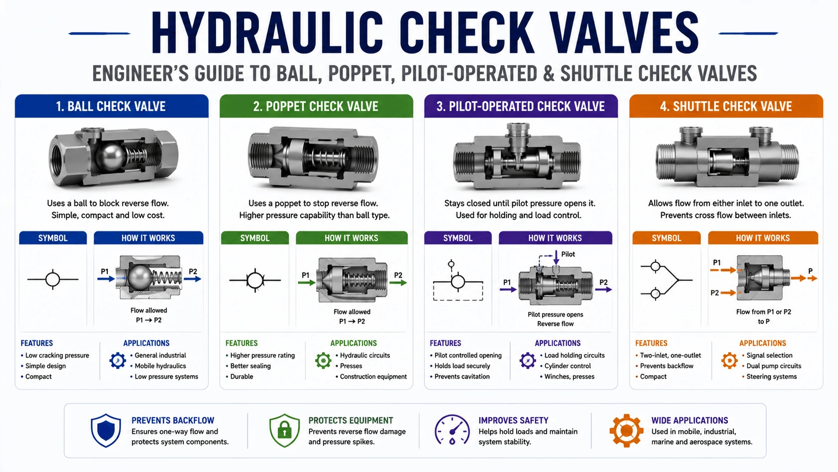
Introduction
A hydraulic check valve is one of the smallest, cheapest components in a hydraulic circuit—and one of the most consequential when it fails. A standard check valve that chatters under a decelerating load can shred its seat in weeks. A pilot-operated check valve specified with the wrong pilot ratio can refuse to open, or worse, open unexpectedly and drop a suspended load. A swing check valve installed in a high-cycle mobile circuit can fatigue its spring and leak back through a pump, causing cavitation on startup.
Despite this, check valves are routinely specified by price and port size alone. Engineers who would never undersize a relief valve often treat the check valve as an afterthought. This guide is written to correct that. It covers every check-valve sub-type used in industrial and mobile hydraulics—ball, poppet, swing, in-line, cartridge, pilot-operated, and shuttle—and gives you the cracking pressures, pilot ratios, leakage classes, cavity standards, failure analysis, and selection framework needed to specify a check valve that actually holds up.
What is a Hydraulic Check Valve?
A hydraulic check valve is a one-way flow control element: it permits free flow in one direction (the “free-flow” or “forward” direction) and blocks reverse flow in the opposite direction. Unlike a directional control valve, it requires no external actuation—it opens and closes automatically in response to pressure differential across the valve.
In a hydraulic circuit, the check valve performs one or more of these duties:
- Reverse-flow protection — preventing fluid (or a load) from moving backward through a circuit branch
- Pump isolation — stopping backflow through an idle pump in dual-pump or redundant-pump systems
- Load holding — locking a cylinder in position against gravity or external force (typically with a pilot-operated check valve)
- Pilot logic — steering pilot signals to the correct port (shuttle valves and pilot check valves)
- Manifold protection — isolating branches so that a failure in one does not propagate to others
Every check valve is defined by a small set of engineering parameters that govern its application:
- Cracking pressure — the differential pressure at which the valve first opens (commonly 0.05, 0.5, 1.5, 3, or 5 bar)
- Nominal size/flow capacity — the maximum flow the valve passes at a defined pressure drop (ΔP), in L/min or GPM
- Pressure rating — the maximum sustained operating pressure (typically 210, 350, or 420 bar; up to 700 bar in high-pressure variants)
- Leakage class — zero-leakage (poppet seat) vs. low-leakage (ball with clearance) vs. metered leakage
- Construction — ball, poppet, disc (swing), guided or unguided
- Mounting — in-line (threaded), cartridge (screw-in cavity), subplate/manifold, or flange
- Pilot option — standard (no pilot) or pilot-operated (pilot-to-open or pilot-to-close)
Understanding these parameters is what separates a check-valve category from a check-valve specification. The sections below cover both.
How a Hydraulic Check Valve Works
All hydraulic check valves operate on the same fundamental principle: a pressure-sensitive sealing element (ball, poppet, or disc) is held against a seat by a combination of spring force and, when reverse flow is present, fluid pressure. Flow in the permitted direction pushes the element off its seat; reverse flow pushes it back onto the seat.
The opening and closing behavior is governed by a force balance:
Forward (opening) direction:
F_fluid_forward > F_spring + F_reverse_pressure + F_friction
Reverse (closing) direction:
The reverse pressure differential, multiplied by the seat area, must exceed any residual forward force and overcome any inertia in the moving element before the valve reseats.
This force balance explains several real-world behaviors:
- Cracking pressure is set by the spring. A 0.5 bar spring means the valve needs 0.5 bar of forward differential pressure just to begin opening. A 5 bar spring is used to deliberately bias flow—for example, ensuring a check valve in a cooling line stays closed until pressure builds upstream.
- Closing is not instantaneous. The poppet or ball has mass and travel distance. A sudden flow reversal can pass through the valve before it reseats, which is why check valves installed immediately downstream of fast-closing directional valves can experience water-hammer.
- Spring rate affects chatter. A heavy spring combined with low forward flow can cause the element to oscillate between open and closed (“chatter”), producing audible noise, seat damage, and pressure spikes. Lighter springs reduce chatter but require lower cracking pressure, which may not suit circuits that need a deliberate pressure bias.
Pilot-operated check valves add a piston that mechanically unseats the poppet when pilot pressure is applied, decoupling the valve’s opening from the load pressure alone. This is covered in detail in Section 5.
Types of Hydraulic Check Valves
Ball Check Valves
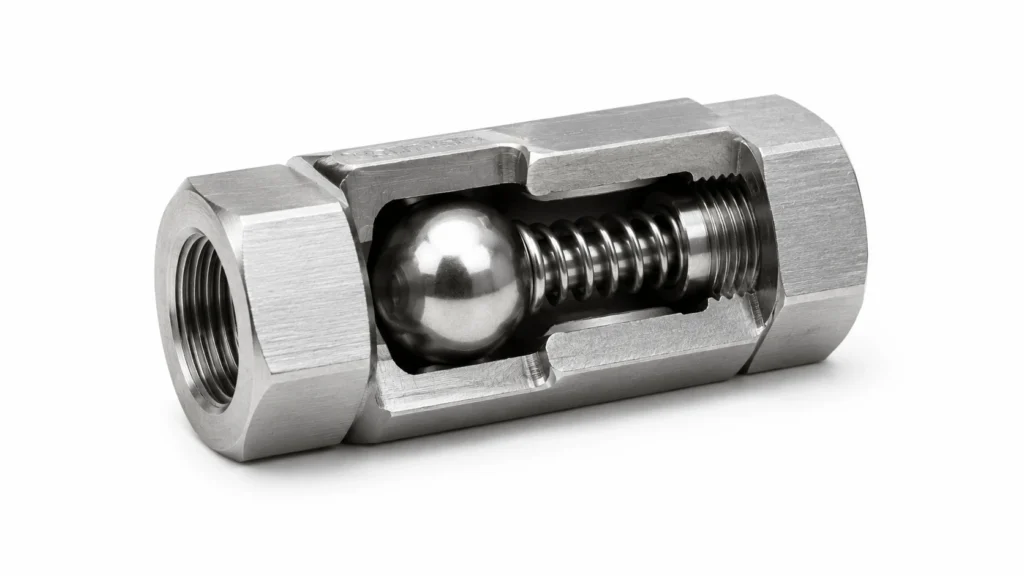
| Characteristic | Typical Value / Behavior |
|---|---|
Sealing element |
Hardened steel or ceramic ball |
Seat material |
Steel, stainless, or bronze (often with a soft insert for low-pressure sealing) |
Cracking pressure |
0.05 – 5 bar (spring-dependent) |
Pressure rating |
up to 700 bar (high-pressure variants) |
Leakage |
Low leakage (ball-to-seat with minimal clearance); not true zero-leak |
Best for |
General-purpose reverse-flow protection, pump isolation, low- to medium-cycle duty |
Poppet Check Valves
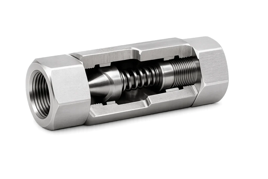
| Characteristic | Typical Value / Behavior |
|---|---|
Sealing element |
Guided poppet (steel) with metal or elastomer seat |
Seat material |
Metal-to-metal, or metal-to-elastomer for zero leakage at low pressure |
Cracking pressure |
0.1 – 5 bar |
Pressure rating |
up to 700 bar |
Leakage |
Zero leakage (with elastomer seat) or near-zero (metal-to-metal) |
Best for |
Load holding, accumulator isolation, safety circuits, any application requiring positive reverse-flow shutoff |
Swing (Disc) Check Valves
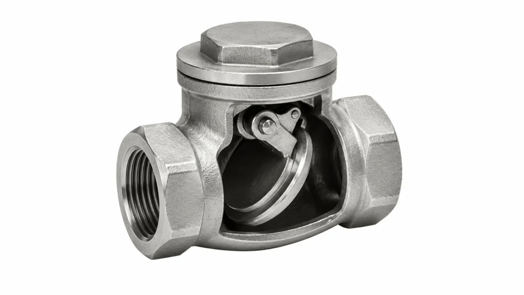
| Characteristic | Typical Value / Behavior |
|---|---|
Sealing element |
Hinged disc (often with elastomer insert) |
Cracking pressure |
Very low (0.02 – 0.3 bar); gravity-assisted or spring-assisted variants available |
Pressure rating |
typically up to 350 bar (lower than ball/poppet) |
Flow capacity |
High—low pressure drop, suitable for large flow lines |
Best for |
Large-flow return lines, tank lines, low-pressure suction isolation |
In-Line vs. Cartridge vs. Subplate Mounting
| Mounting Style | Description | Typical Use |
|---|---|---|
In-line (threaded) |
Threaded end fittings (SAE, BSPP, NPT, metric) for hose or tube connection |
Hose assemblies, retrofit, low-density plumbing |
Cartridge (screw-in) |
Threaded insert that screws into a machined cavity in a manifold block |
Integrated manifolds, mobile equipment, compact OEM packages |
Subplate / manifold |
Mounts on an ISO 4401 / CETOP interface or a custom manifold pad |
Industrial systems with stacked valve assemblies |
Pilot-Operated Check Valves (Pilot-to-Open)
Working Principle
| State | Pilot Pressure | Load Pressure | Poppet Position | Result |
|---|---|---|---|---|
Holding |
0 bar |
High (load) |
Seated |
Load locked, zero leakage |
Releasing |
Applied (sufficient to overcome load) |
High (load) |
Lifted by pilot piston |
Controlled reverse flow, load lowers |
Free flow |
Not applied |
Forward differential |
Lifted by flow |
Normal forward flow permitted |
Pilot Ratio and Why It Matters
| Pilot Ratio | Pilot Pressure to Open (at 200 bar load) | When to Choose |
|---|---|---|
3:1 |
≈ 66 bar |
High available pilot pressure, want maximum seating force for safety |
4:1 |
≈ 50 bar |
General-purpose load holding, balanced choice |
8:1 |
≈ 25 bar |
Limited pilot pressure, low-pressure systems, or where pilot signal is shared |
Selecting the wrong pilot ratio causes two distinct failure modes:
- Ratio too low (e.g., 3:1 when 8:1 is needed): The available pilot pressure cannot open the valve against the load. The cylinder refuses to retract, or retracts only after the relief valve dumps the load—wasting energy and generating heat.
- Ratio too high (e.g., 8:1 when 3:1 is needed): The valve opens too easily. A small pressure transient in the pilot line can release the load unintentionally, and the valve may chatter under deceleration. In overrunning-load applications (crane booms, presses), an excessive pilot ratio can allow the load to “run away” faster than the pump can supply fluid.
The correct pilot ratio is selected by working backward from the minimum guaranteed pilot pressure in the circuit and the maximum expected load pressure, with a safety margin. For most industrial load-holding applications, a 4:1 ratio is the default.
Pilot-to-Open vs. Pilot-to-Close
Most pilot-operated check valves are pilot-to-open (the pilot unseats the poppet to allow reverse flow). A less common variant is the pilot-to-close check valve, in which the pilot forces the poppet closed—used in safety circuits where a control pressure must positively block a flow path. The two are not interchangeable, and specifying the wrong one is a serious design error. Pilot-to-open dominates load-holding duty; pilot-to-close appears in brake and safety interlock circuits.
Shuttle Valves (OR Logic)
A shuttle valve is a check-valve cousin that selects the higher of two input pressures and routes it to a single output. Internally, it contains a small piston or ball that shifts between two seats depending on which input is at higher pressure.
| Characteristic | Shuttle Valve |
|---|---|
Function |
Select higher of two pressures (OR logic) |
Ports |
3 (two inlets, one outlet) |
Symbol |
Two check valves pointing toward a common outlet |
Typical use |
Brake circuits (apply brakes from either of two pedal circuits), redundant pilot supply, fail-safe control |
A shuttle valve looks like two check valves sharing an output, and that is essentially what it is. The distinction matters because engineers sometimes attempt to use two standard check valves instead of a true shuttle valve—this works only if the cracking pressures are perfectly matched and the inlet pressures differ significantly; otherwise one input can dominate and the other is shut out. A true shuttle valve with a free-floating piston is the correct element whenever two pressure sources must be combined with OR logic.
Shuttle valves are common in:
- Brake circuits — front and rear brake pedals both apply the same brake; whichever is pressed harder wins
- Redundant pilot supply — a primary and backup pilot source feed the same pilot-operated valve
- Fail-safe control — a manual override and an automatic signal both command the same function
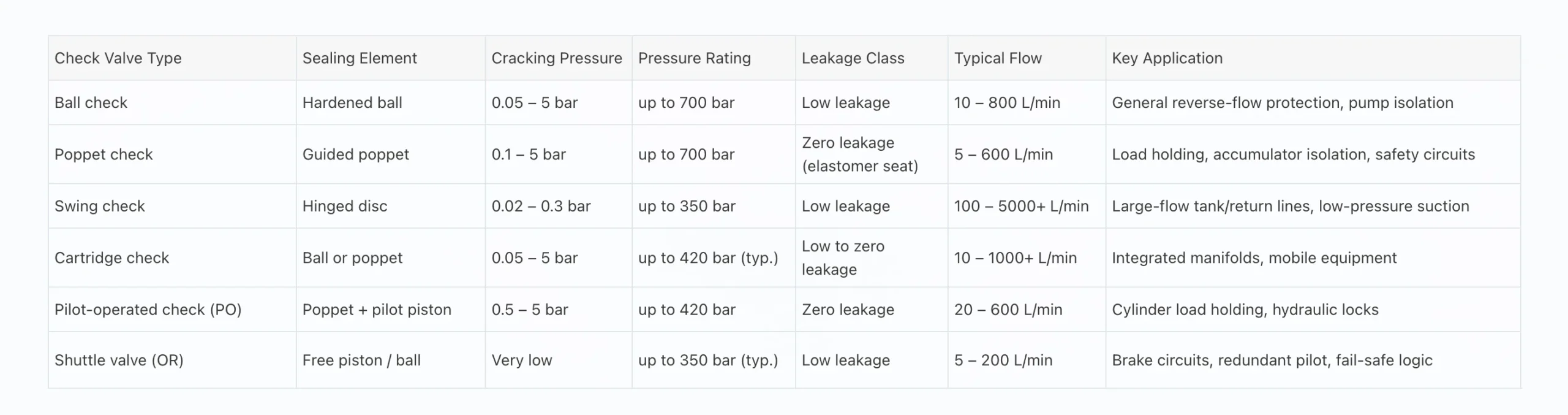
Hydraulic Check Valve Comparison Table
Cracking Pressure: Selection and Engineering
Common Cracking Pressure Bands and Their Applications
| Cracking Pressure | Engineering Purpose | Typical Application |
|---|---|---|
0.05 bar (essentially zero) |
Open under any forward flow; minimize pressure drop |
Tank return lines, suction isolation |
0.5 bar |
Slight bias to keep valve closed at rest, prevent siphoning |
Pump isolation, general in-line check |
1.5 bar |
Maintain a small positive pressure upstream; prevent drain-back |
Cooling lines, filter bypass, accumulator precharge retention |
3 bar |
Deliberate bias; ensure upstream pressure builds before flow |
Brake-release circuits, sequence-like behavior |
5 bar |
Strong bias; valve stays closed until meaningful pressure exists |
Holding circuits, cooling-system isolation, pilot-bias applications |
Common Cracking-Pressure Mistakes
- Specifying 0.5 bar when 0.05 bar is needed in a suction or return line. The 0.5 bar spring causes cavitation at the pump inlet or unnecessary back-pressure in the tank line.
- Specifying too low a cracking pressure in a pump-isolation check. With no spring bias, the ball or poppet can flutter under vibration, allowing brief reverse flow that slowly drains the pump line and causes dry starts.
- Treating cracking pressure as a sealed value. In reality, the valve begins to crack at the rated pressure and reaches full opening at a higher pressure (typically 1.5 – 3× cracking, depending on spring design). The full-open ΔP is what matters for sizing, not just the cracking value.
The correct selection logic: identify the minimum differential pressure that will exist in normal operation when flow should be permitted, then choose a cracking pressure comfortably below that (typically 30 – 50% of the minimum forward ΔP) so the valve opens fully under normal flow and reseats positively when forward flow stops.
Sizing a Hydraulic Check Valve (Pressure Drop & Flow)
A check valve must be sized for two conditions simultaneously:
- Rated flow at acceptable pressure drop (ΔP). The valve’s nominal size is the size at which ΔP remains reasonable—typically ≤ 1 – 2 bar for a check valve (lower than the ≤ 5 bar target for directional valves, because check valves are often in low-ΔP paths like return lines or pump discharge).
- Pressure rating ≥ maximum system pressure, including spikes. As with any hydraulic component, transients from valve shifts and load decelerations can reach 1.25 – 1.5× the relief valve setting.
Pressure Drop Behavior
Check-valve ΔP is not linear with flow. It follows approximately:
ΔP ≈ cracking pressure + k × (flow)²
where k is a valve-specific constant determined by internal geometry. This quadratic behavior means doubling the flow roughly quadruples the ΔP above cracking—which is why selecting a check valve “close to rated flow” can produce surprisingly high pressure drop and heat generation.
Sizing Example
Consider a pump discharge line with:
- Rated flow: 120 L/min
- Maximum system pressure: 280 bar
- Desired ΔP at rated flow: ≤ 1.5 bar total
A check valve with 0.5 bar cracking and a nominal 150 L/min rating will typically show ΔP ≈ 1.0 – 1.3 bar at 120 L/min—acceptable. The same valve rated at 80 L/min would show ΔP ≈ 2.8 – 3.5 bar at 120 L/min—excessive, generating heat and wasting energy.
A practical engineering rule: size the check valve one nominal size above the line size for low-ΔP applications (return lines, suction isolation), and at line size for pressure-line applications where ΔP is less critical.
Mounting Standards & Cavity Specifications
Cartridge and subplate check valves are interchangeable only when their mounting interface matches. The relevant standards are:
| Standard | Scope | Common Sizes |
|---|---|---|
SAE J1926 / ISO 11926 |
Threaded cartridge cavities (UNF threads, dominant in North America) |
-8, -10, -12, -16, -20, -24 (and metric equivalents) |
ISO 7368 |
Two-port logic cartridge cavities (cover-controlled, high flow) |
25, 32, 40, 50, 63 mm bore |
ISO 4401 / CETOP RP121H |
Subplate-mounted directional and check valves |
NG6 (CETOP 03), NG10 (CETOP 05), NG16 (CETOP 07), NG25 (CETOP 08) |
NFPA D03 / D05 / D07 / D08 |
North American equivalent of CETOP 03 / 05 / 07 / 08 |
Same flow/size class |
A check valve specified as “ISO 7368-25” will fit any 25 mm logic cartridge cavity worldwide. A cartridge check valve marked “-12 SAE” will fit any -12 UNF cavity. Specifying the mounting interface is the first procurement decision—the cavity defines what fits, and the internal element defines what it does. Mismatched cavity standards are one of the most common sourcing errors in aftermarket check-valve procurement.
For in-line check valves, the relevant interface is the port fitting standard: SAE 4-bolt flange (SAE J518 / ISO 6162), BSPP (ISO 228), NPT, or metric. Port size and pressure class must be matched to the hose or tube assembly; a check valve with the wrong port standard is unusable regardless of its internal specification.
Common Hydraulic Check Valve Failures
Check valve failures are usually symptoms of improper specification or system contamination rather than defects in the valve itself. The most common failure modes:
Chatter (Audible Hammering)
- Causes: Spring rate too high for the forward flow; valve cycles between open and closed as flow oscillates around the cracking point; system deceleration mass slamming the poppet closed
- Symptoms: Loud knocking, vibration, pressure spikes, rapid seat wear
- Most affected: Ball and poppet checks in pump-discharge and deceleration circuits; swing checks in high-cycle service
Reverse Leakage (Failure to Hold)
- Causes: Contamination trapped on the seat (poppet types), worn seat, scored ball, fatigue-relieved spring, elastomer seat hardened or chemically attacked
- Symptoms: Load drifts, pump loses prime, accumulator bleeds down overnight
- Most affected: Poppet checks in load-holding duty, ball checks in pump-isolation duty
Failure to Open (Stuck Closed)
- Causes: Contamination wedged in the poppet/seat, corrosion, varnish from degraded oil, pilot pressure insufficient (pilot-operated types), pilot ratio mismatched to load
- Symptoms: Cylinder refuses to retract, pump deadheads, motor stalls
- Most affected: Pilot-operated checks in load-holding circuits
Premature Fatigue (Spring Failure)
- Causes: High cycle counts exceeding spring design life, fluid compatibility issue with spring material, vibration
- Symptoms: Cracking pressure drifts downward, valve opens at lower pressure than specified, and eventual reverse leakage
- Most affected: Spring-loaded ball and poppet checks in high-cycle mobile equipment
Water-Hammer on Closing
- Causes: Long line downstream of the check valve with significant fluid mass; fast-closing directional valve creating sudden flow reversal; swing check with slow reseat
- Symptoms: Pressure spike on closing, audible “thump,” hose whip, joint fatigue
- Most affected: Swing checks, any check installed near a fast directional valve
Troubleshooting Guide
| Symptom | Likely Check-Valve Causes | Diagnostic Action |
|---|---|---|
Load drifts down overnight |
Poppet seat contamination; worn seat; failed spring |
Isolate check valve, inspect seat and poppet; measure reverse leakage at rated pressure |
Cylinder will not retract |
PO check pilot pressure too low; pilot ratio mismatched; pilot piston jammed |
Measure pilot pressure at the PO check; calculate required pilot = load ÷ ratio; inspect pilot piston |
Loud knocking at pump startup |
Check valve chattering; spring rate mismatched to flow |
Measure flow and ΔP; consider lower cracking pressure or larger size |
Pump loses prime overnight |
Pump-isolation check leaking back; worn ball/seat |
Install pressure gauge at pump discharge; check for decay overnight |
Pressure spike on directional valve close |
Check valve water-hammer; slow reseat; long line mass |
Add accumulator or pulsation dampener; consider faster-closing poppet check |
Check valve runs hot |
Excessive ΔP from undersizing; continuous throttling |
Measure ΔP at operating flow; verify size against flow curve |
Accumulator bleeds down |
Isolation check leaking; elastomer seat hardened |
Isolate check; measure leakage; replace seat or entire valve |
Brake circuit applies intermittently |
Shuttle valve sticking; contamination between piston and body |
Disassemble shuttle; clean and inspect bore; verify free piston motion |
How to Select the Right Hydraulic Check Valve
A structured selection process prevents both over-engineering and the far more common problem of under-engineering. Work through these steps in order:
1. Define the Function
Identify what the check valve must do. The function fixes the sub-type:
- General reverse-flow protection → ball check
- Zero-leakage reverse-flow protection → poppet check
- Load holding on a cylinder → pilot-operated check (pilot-to-open)
- Large-flow, low-pressure return/suction → swing check
- OR logic between two pressure sources → shuttle valve
2. Establish Operating Parameters
- Maximum sustained pressure (and expected spikes, typically 1.25× relief setting)
- Maximum and minimum forward flow
- Maximum reverse pressure (the load or back-pressure the valve must hold)
- Fluid type and viscosity grade (ISO VG 32 / 46 / 68)
- Cleanliness target (ISO 4406 code)
- Ambient and fluid temperature range
3. Choose Cracking Pressure
Select a cracking pressure 30 – 50% below the minimum forward differential pressure expected in normal operation. Match the band to the application (see Section 8).
4. Confirm Pressure Drop at Rated Flow
At your operating flow, confirm ΔP is within an acceptable range. For check valves, target ΔP ≤ 1 – 2 bar at rated flow. Excessive ΔP generates heat; undersizing is the most common cause.
5. Select Leakage Class
- Zero leakage required (load holding, accumulator isolation, safety) → poppet with elastomer seat
- Low leakage acceptable (pump isolation, general protection) → ball check
6. For Pilot-Operated Checks, Select Pilot Ratio
Calculate the required pilot pressure to open at maximum load:
Required pilot pressure = (maximum load pressure) ÷ (pilot ratio)
Choose a pilot ratio so that the minimum guaranteed pilot pressure in your circuit exceeds the required opening pressure with a safety margin (typically 1.3×). For most industrial load-holding applications, 4:1 is the default; for low-pressure or shared-pilot circuits, 8:1.
7. Choose Mounting Style and Cavity Standard
- Cartridge → SAE J1926 / ISO 11926 (threaded) or ISO 7368 (logic)
- Subplate → ISO 4401 / CETOP (NG6, NG10, NG16, NG25)
- In-line → port standard (SAE flange, BSPP, NPT, metric)
Specifying the cavity standard is the first procurement decision—it defines interchangeability across manufacturers.
8. Evaluate Contamination Tolerance
Pilot-operated and poppet check valves require cleaner fluid than ball checks. If your system filtration cannot achieve ISO 4406 18/16/13 or better, either upgrade filtration or select a more contamination-tolerant ball check where the application allows.
9. Procurement Considerations
- Lead time for spare cartridges and seal kits
- Availability of equivalent valves from multiple manufacturers (cavity-standard interchangeability)
- Documentation: symbol, cross-section, flow/ΔP curves, leakage class
- Seal material compatibility with your fluid (NBR, FKM, HNBR, EPDM)
- Warranty and field-support network
Maintenance Best Practices
- Maintain oil cleanliness to ISO 4406 18/16/13 or better, particularly for poppet and pilot-operated checks. Contamination is the leading cause of reverse leakage in poppet checks.
- Replace filters on schedule and monitor differential-pressure indicators. A bypassing filter lets the very contamination that ruins check-valve seats circulate through the system.
- Verify cracking pressure annually with a calibrated bench test—drift indicates spring fatigue.
- Inspect pilot-operated checks for smooth pilot-piston motion; a sticking pilot piston causes intermittent load release.
- Monitor temperature—sustained operation above 60°C hardens elastomer seats and accelerates spring fatigue.
- Sample oil quarterly for particle count, water content, and viscosity; trend the results. A rising particle count is a leading indicator of imminent check-valve failure.
- Keep spare cartridges for critical load-holding checks. Cartridge interchangeability means a spare on the shelf can restore operation in minutes.
An industry benchmark: in systems with well-controlled contamination (ISO 4406 18/16/13 or better), a quality poppet check valve in load-holding duty routinely exceeds 10,000 operating hours. In systems at ISO 22/20/17 or worse, the same valve can begin to leak reverse within 2,000 hours.
Industrial Applications
Different industries deploy check-valve sub-types in characteristic ways based on pressure, flow, duty cycle, and load-holding requirements:
| Industry | Dominant Check-Valve Types | Why |
|---|---|---|
Construction equipment |
Cartridge ball checks, pilot-operated checks (4:1 ratio) |
Compact manifolds, load holding on booms and buckets, mobile duty |
Agricultural machinery |
In-line ball checks, shuttle valves (brake circuits) |
Cost-sensitive, moderate pressure, redundant control functions |
Manufacturing / presses |
Pilot-operated poppet checks (3:1 – 4:1), subplate checks |
Precise load holding, high cycle counts, safety-critical |
Mining equipment |
Cartridge poppet checks, logic check valves |
High pressure, harsh environment, high flow, contamination-tolerant designs |
Marine hydraulics |
Stainless ball checks, pilot-operated checks |
Corrosion resistance, load holding for cranes and hatch covers |
Oil & gas |
Cartridge poppet checks, high-pressure ball checks |
350 – 700 bar systems, accumulator isolation, blowout-preventer hydraulics |
Wind energy |
Pilot-operated checks for blade pitch and brake |
Reliability-critical, fail-safe holding, long maintenance intervals |