Hydraulic Pump Parts: Complete Component Guide for Engineers

Table of Contents

A hydraulic pump fails. You tear it down. Now you are staring at thirty scattered pieces on the workbench and wondering which ones actually need replacing, which might clean up for reuse, and which you should have inspected six months ago. Understanding hydraulic pump parts at the component level changes how you approach maintenance. It turns guesswork into a process. It cuts unplanned downtime. It stops you from ordering the wrong kit and waiting three weeks for a delivery that does not fit.
 
This guide breaks down components by pump type. Gear, piston, and vane each wear differently. Each has its own critical components and its own replacement logic. The goal is simple. Give you enough detail to identify parts correctly, judge wear accurately, and source replacements without overbuying.

Gear Pump Components
Gear Pump Components
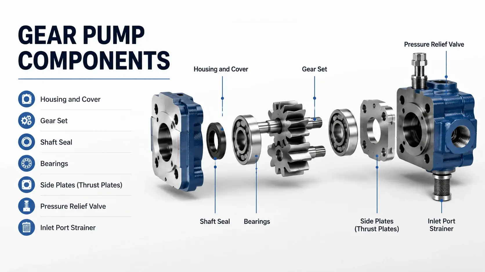
Gear pumps contain the fewest hydraulic pump parts of any major type, which explains their popularity in applications under 210 bar. A typical external gear pump has seven core component groups.

Housing and Cover

Cast iron or aluminum depending on pressure class. The bore tolerance holds the gear outer diameter (OD) within 0.025 to 0.050 mm radial clearance. Pitting or scoring on the bore wall means the housing is done. Some high-pressure designs use a replaceable bushing pressed into the housing bore, which extends service life considerably.

Gear Set

Two meshing gears, usually through-hardened to HRC 58-62. The drive gear keys to the input shaft. The idler runs free in the housing bore or on a needle bearing. Tooth flank wear shows as increased tip clearance and reduced volumetric efficiency. Measure tooth thickness at the pitch line. Anything below 90% of original dimension warrants replacement.

Shaft Seal

NBR for mineral oil up to 100C, FKM/Viton for higher temps or synthetic fluids. A hardened steel sleeve under the seal lip (called a wear sleeve) prevents shaft scoring. If the groove in the sleeve exceeds 0.2 mm depth, replace the sleeve along with the seal.

Bearings

Sleeve bearings in low-pressure designs, tapered roller or ball bearings in units rated above 175 bar. Check radial play with a dial indicator. More than 0.05 mm axial or radial movement means new bearings.

Side Plates (Thrust Plates)

These take the axial thrust from gear mesh pressure. Bronze or sintered iron with a lead-tin overlay in better designs. Look for scoring parallel to the gear face. Deep grooves indicate contamination ingestion. Replace in pairs.

Pressure Relief Valve

Built into the cover on many integrated power unit pumps. Spring, poppet, and seat. Inspect the seat for erosion. A pitted seat causes the valve to crack open early and starves the system of flow.

Inlet Port Strainer

Mesh screen, typically 60 to 150 micron rating. Clogged strainers cause cavitation before anything else wears out. Clean or replace every 500 hours in dirty environments.
 
These components share a failure pattern. Contamination kills the side plates and gear flanks first. Heat degrades the seal and thins the oil film in the bearings. Overspeed loads the gear teeth beyond the design Hertzian contact stress. Knowing which stress hits your pump tells you which parts to inspect first.

Piston Pump Components

Piston Pump Components
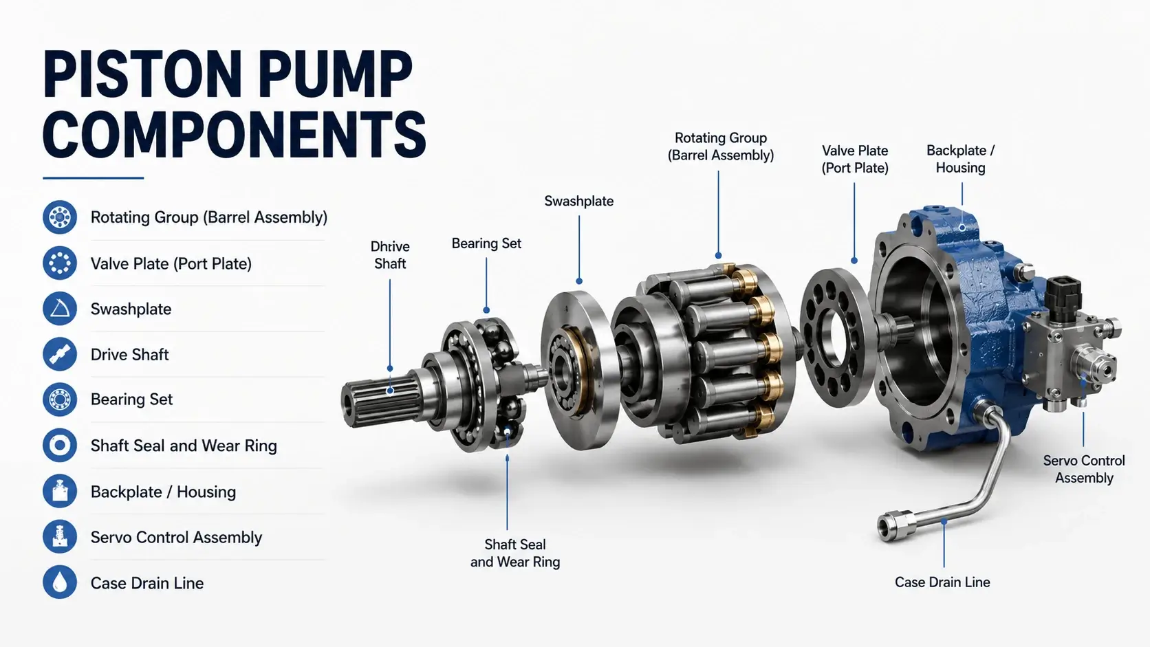
Axial piston pumps pack more components into a smaller envelope than gear pumps, and those parts operate at higher stresses. A typical swashplate-design piston pump has nine major assemblies.

Rotating Group (Barrel Assembly)

Cylinder block, pistons, slipper shoes, and slipper retainer plate. The cylinder block is usually ductile iron or bronze-over-iron. Piston bores hold a honed finish below 0.4 microns Ra. Taper or out-of-round beyond 0.008 mm per 25 mm of bore diameter means the block is scrap. Pistons are case-hardened steel, typically 15Rc surface hardness. The spherical socket that mates to the slipper shoe shows fretting corrosion if the pump ran hot or dry. Slipper shoes run against the swashplate. The running face needs a minimum 0.8 mm thickness. Any breakthrough to the steel backing means discard.

Valve Plate (Port Plate)

The bridge between high-pressure and low-pressure ports. Mild steel or ductile iron with a hard chrome or oxide coating on the sealing lands. This is the single most replaced part in piston pump service. Check the kidney ports for erosion. A rounded edge on the high-pressure port lip indicates cavitation damage from low inlet pressure. Flatness matters. Lap on a granite plate if warpage exceeds 0.005 mm across the face.

Swashplate

Fixed-angle or variable. Variable swashplates include a servo piston and bias spring assembly. The running surface contacts the slipper shoes. Look for scoring tracks aligned with the piston pitch circle diameter (PCD). Deep tracks mean the slippers were sliding instead of rolling, usually from low fluid viscosity or cold starts. Surface finish should stay below 0.2 microns Ra. Regrind or replace.

Drive Shaft

Alloy steel, spline-driven. The spline teeth carry torque. Check for fretting at the coupling interface and twist deformation if the pump stalled under load. Shaft straightness should be within 0.025 mm TIR. Bend it back once. After that, the fatigue life is unpredictable.

Bearing Set

Usually a tapered roller bearing pair handling combined axial and radial load, plus a cylindrical roller at the nose end for radial support only. Preload is critical. Factory specs range from 0.02 to 0.08 mm axial clearance depending on model. Loose preload accelerates rotating group eccentricity and valve plate edge loading. Tight preload generates heat and shortens bearing life dramatically.

Shaft Seal and Wear Ring

Similar to gear pumps but operating at higher shaft surface speeds. Viton or fluoroelastomer standard. Some high-speed designs use a PTFE-lipped seal backed by an O-ring energizer. The wear ring groove limit is tighter here, 0.1 mm max, because shaft speed multiplies the lip temperature rise.

Backplate / Housing

Contains the valve plate seat, bearing bores, and servo cylinder bore in variable-displacement models. The valve plate seating surface must be flat within 0.01 mm. Housing bore for the barrel pilot diameter typically allows 0.02 to 0.05 mm radial clearance. Egg-shaped bore clearance means misalignment during high-pressure operation.

Servo Control Assembly

Found on variable displacement pumps only. Includes the control piston, control spool, bias spring, and limiter screws. Stiction in the control spool causes displacement drift or unstable flow output. Polish the spool lands with 600-grit paper if minor scoring exists. Replace if the land diameter varies more than 0.005 mm.

Case Drain Line

Not a part you buy, but a passage that kills pumps when blocked. Internal leakage from the rotating group and bearings must exit freely. Case drain flow above 5% of rated flow signals worn rotating group or valve plate. Above 10% means rebuild immediately.
 
Piston pump assemblies fail in predictable stages. Stage one, the valve plate loses flatness and leaks high-pressure oil to case drain. Stage two, the slipper shoes thin and the swashplate scores. Stage three, the cylinder block tapers and the whole rotating group scraps. Catching the problem at stage one costs a valve plate. Waiting until stage three costs a full rotating group plus the time down.

Vane Pump Components

Vane Pump Components
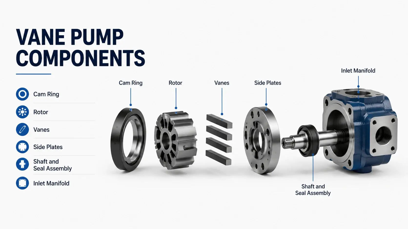
Vane pumps sit between gear and piston pumps in both complexity and component count. A balanced vane pump has six primary assemblies.

Cam Ring

The stationary elliptical track that the vanes follow. Cast iron or ductile iron in standard pumps, hardened steel or coated in high-pressure models above 140 bar. The cam profile surface finish directly affects vane life. Anything rougher than 0.4 microns Ra accelerates vane tip wear. Check for ovality. Out-of-round beyond 0.05 mm on the minor axis causes vane chatter and noise.

Rotor

Holds the vane slots radially around the shaft center. Machined from steel or ductile iron. Slot width tolerance is tight, typically +0.010/-0.000 mm relative to vane thickness. Wider slots let vanes rattle and break the slot edges. This is the most common reason rotors get scrapped. Inspect slot sidewalls for scoring. Minor polishing with fine emery cloth works. Deep grooves mean replace.

Vanes

The consumable part. Rectangular strips of hardened tool steel or impregnated carbon graphite in some low-noise designs. Vane length decreases as the tip wears against the cam ring. Measure vane length. Shorter than 95% of nominal means replace the full set, not just the short ones. Mixed vane lengths cause unbalanced radial loading on the rotor and bearing.

Side Plates

One on each side of the rotor-vane assembly. Bronze or sintered iron. Pressure-balanced designs route system pressure to the back of the side plates to push them against the rotor faces. This minimizes internal leakage but puts the full plate load on the plate material. Look for the same scoring pattern described for gear pump side plates. Replace in pairs.

Shaft and Seal Assembly

Keyed or splined shaft in a bearing-supported front cover. Seal selection follows the same logic as gear and piston pumps. Note that vane pumps generate significant radial load at the inlet transition zone where vanes extend furthest. Bearing preload matters more here than the shaft speed suggests.

Inlet Manifold

Cast into the housing on integral-configuration pumps, bolted on as a separate casting in others. The inlet passage cross-section area must stay unrestricted. A common oversight during reassembly is pinching the inlet O-ring or installing the gasket offset, which creates a flow restriction that mimics cavitation.
 
Vane pump assemblies follow a wear sequence. Vanes shorten first. Then the cam ring loses profile accuracy at the major and minor diameter transitions. Then the rotor slots widen from vane side-loading. Then the side plates score. A maintenance program that measures vane length every 1,000 operating hours catches the chain at the cheapest link.

Common Failure Modes Across All Pump Types

Certain failure patterns show up regardless of pump type. Recognizing the pattern points to the root cause faster than measuring every dimension.

Contamination Damage

Fine particles below 40 microns act as lapping compound between sliding surfaces. You see polished wear tracks on valve plates, scored side plates, and abrasive wear on gear tooth flanks. ISO 4406 cleanliness codes tell the story. Operating consistently above 18/16/13 accelerates wear on every internal part by a factor of three to five compared to 16/14/11 or cleaner oil.

Cavitation Erosion

Low inlet pressure or restricted supply lines cause vapor bubbles to collapse near the pumping elements. The damage looks like pitting, not scoring. On piston pumps, it attacks the valve plate kidney port edges. On gear pumps, it erodes the housing near the inlet cavity. On vane pumps, it pits the cam ring at the inlet transition zone. Fix the inlet line before replacing parts, or the new ones fail the same way.

Heat Degradation

Sustained operation above 80C accelerates seal hardening, oil oxidation, and bearing lubrication breakdown. The viscosity drops, the film thickness shrinks, and metal-to-metal contact increases. Shaft seals harden and crack. Bearings develop discoloration races from overheated lubricant. If the pump case feels too hot to hold your hand on for five seconds, the internal components are running above their design temperature window.

Overpressure Loading

Relief valve malfunction or system spikes subject parts to pressures above the design rating. Piston pump valve plates warp. Gear pump side plates deflect. Vane pump cam rings crack at the major axis. The damage is often invisible until teardown. Install a test gauge temporarily if you suspect overpressure events.

Fatigue Cycling

Frequent pressure reversals or direction changes fatigue the rotating elements. Shaft splines fret and wear. Bearing races spall. Piston bore edges chamfer from repeated impact. Applications with cycle counts above 10 million per year need a pump sized for the duty cycle, not just the peak pressure and flow.

Wear Limits and Inspection Criteria

Numbers make inspection objective. Here are the thresholds that separate reusable from scrap components across all three pump types.
Component Measurement Reject Limit Method
Gear tooth thickness
Pitch line
<90% of nominal
Micrometer
Gear housing bore ID
Radial clearance
>0.050 mm total
Bore gauge
Side plate scoring depth
Depth gauge
>0.05 mm
Depth micrometer
Piston bore taper
Per 25 mm bore
>0.008 mm
Bore gauge
Piston bore roundness
Full depth
>0.005 mm
Three-point gauge
Slipper shoe thickness
Minimum
<0.8 mm
Caliper
Valve plate flatness
Full face
>0.005 mm TIR
Optical flat + feeler
Swashplate surface finish
Ra value
>0.2 microns
Profilometer
Shaft straightness
TIR
>0.025 mm
V-blocks + dial indicator
Bearing radial play
Axial/radial
>0.05 mm
Dial indicator
Vane length
Overall
<95% of nominal
Caliper
Rotor slot width
Clearance
>0.030 mm total
Plug gauge
Cam ring roundness
Minor axis
>0.050 mm deviation
CMM or bore gauge
Seal wear ring groove
Depth
>0.2 mm (gear), 0.1 mm (piston)
Depth micrometer

These limits come from pump manufacturer service manuals and field rebuild data. Running parts beyond these thresholds reduces rebuild life by 40 to 60 percent on average. The few hundred dollars saved on a borderline part rarely offsets the labor hours lost to a premature re-failure.

Materials and Metallurgy

What a part is made of determines how it wears, how long it lasts, and whether an aftermarket copy will match the OEM performance. Here is what you will find inside each pump type.

Gear Pump Materials

  • Housing: Gray cast iron (FC200 class) for standard pressure, aluminum alloy for mobile apps under 175 bar
  • Gears: AISI 8620 or 9310 carburized steel, HRC 58-62 surface, HRC 28-35 core
  • Side plates: Sintered iron (FC-0205 grade) or leaded bronze (C93200) for higher pressure
  • Shafts: AISI 1045 or 4140, induction-hardened at the seal area
  • Seals: NBR (Buna-N) standard, FKM for heat or PAO fluids

Piston Pump Materials

  • Cylinder block: Ductile iron (FCD600) or manganese bronze (C95400) for seawater compatibility
  • Pistons: Case-hardened alloy steel (AISI 8620), 58-62 HRC surface
  • Slipper shoes: Through-hardened tool steel (AISI 52100) or carburized 8620
  • Valve plate: Ductile iron with hard chrome plate (0.03-0.05 mm thickness) or black oxide
  • Swashplate: Forged steel (AISI 4140 or 4340), induction-hardened track, HRC 50-55
  • Bearings: Tapered roller (ISO Class 3 or better), matched sets

Vane Pump Materials

  • Cam ring: Ductile iron (FCD450) standard, hardened steel (HRC 45-50) for high-pressure models
  • Rotor: Carbon steel (S45C) or ductile iron, induction-hardened slot edges
  • Vanes: High-speed tool steel (SKH-51/AISI M2, HRC 60-65) or impregnated graphite carbon
  • Side plates: Leaded tin bronze (C93200) or dual-metal (steel backing + bronze overlay)

Aftermarket hydraulic pump parts vary widely in material quality. Reputable suppliers specify the alloy grade and heat treatment on the datasheet. Budget listings that say “hardened steel” without an AISI number or hardness value are a gamble. For critical rotating group components, the price difference between verified-spec aftermarket and mystery-metal copies rarely exceeds fifteen percent. That fifteen percent buys predictability.

Sourcing Hydraulic Pump Parts

Four channels exist for obtaining replacement parts. Each has a place depending on urgency, budget, and criticality.

OEM Direct

Highest cost, longest lead time (four to twelve weeks for non-stock items), guaranteed specification match. Required for warranty claims on equipment still under coverage. Best option when the part has proprietary geometry or coating that aftermarket sources cannot replicate.

Authorized Distributor Stock

Moderate cost premium over OEM direct, faster availability for common parts. Distributors carry rebuild kits and rotating groups for popular pump models. Good balance of speed and traceability. Ask for the certificate of analysis (CoA) on critical rotating components.

Independent Aftermarket

Widest price range. Quality varies from excellent to unacceptable. Some machine shops reverse-engineer and improve upon OEM designs with better materials or coatings. Others cast parts from unspecified alloys with minimal QC. Due diligence means checking material certifications, requesting hardness test reports, and starting with a small trial order before committing to volume.

Custom Manufacture

For obsolete pumps where no off-the-shelf parts exist. Requires a sample part or complete engineering drawing. Machine shops with hydraulic experience can reproduce gears, valve plates, and housings from scratch. Lead time runs six to ten weeks. Cost is high but lower than retrofitting a different pump model into an existing system.

Practical sourcing advice. Keep a rebuild kit for each critical pump model on your shelf. The kit cost sits between 80 and 800 depending on pump type and size. Having it available when the pump fails converts a three-week downtime event into an eight-hour repair. For high-utilization equipment (over 4,000 hours per year), stock the full rotating group as well. That is the part with the longest lead time and the highest consequence if unavailable.

Identifying Parts Correctly
Identifying Parts Correctly
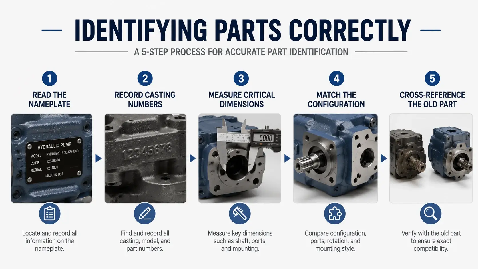
Wrong parts cost more than no parts. You waste money on the purchase, waste time discovering the mismatch, and waste credibility with whoever approved the purchase order. Follow this identification sequence.

Step 1: Read the Nameplate

Model number, serial number, manufacture date, and pressure/flow rating. Photograph the plate. The text rubs off over time and you will need the image later.

Step 2: Record Casting Numbers

Major castings (housing, cover, backplate) have raised or stamped part numbers. Write these down. They often differ from the assembly model number and are what the parts catalog actually references.

Step 3: Measure Critical Dimensions

Mounting pattern (bolt circle diameter and hole size), shaft diameter and keyway size, port thread type and size (SAE J1926, ISO 6149, BSPP, NPT), and overall envelope. Compare these against the catalog drawing before ordering. Two pumps with the same model prefix sometimes have different shafts or port configurations depending on the production year.

Step 4: Match the Configuration

Variable vs fixed displacement, clockwise vs counterclockwise rotation (facing the shaft), and port location (left/right, top/bottom). A variable-displacement backplate will not fit a fixed-displacement housing even if the bolt pattern matches.

Step 5: Cross-Reference the Old Part

If you have the removed component, measure it directly. Thickness, OD, ID, bore spacing, tooth count, spline count, and keyway dimensions. Send these measurements to the supplier with your order. Good suppliers catch mismatches before shipping.
Take photos at each teardown step. Tag parts in sequence so reassembly follows the same orientation. A simple Sharpie numbering system on each component saves confusion when thirty similar-looking pieces cover the bench.

FAQ

What are the main parts of a hydraulic pump?

It depends on the pump type. Gear pumps contain a housing, gear set, shaft seal, bearings, side plates, and often an integrated relief valve. Piston pumps add a rotating group (cylinder block, pistons, slipper shoes), valve plate, swashplate, and on variable models, a servo control assembly. Vane pumps use a cam ring, rotor with vane slots, sliding vanes, and side plates. All three types share seals, bearings, and a shaft as common components.

Which hydraulic pump parts fail most often?

Seals and valve plates lead the failure frequency list. Shaft seals degrade from heat, age, and shaft wear grooves. Valve plates lose flatness from thermal cycling and pressure spikes, causing internal leakage and efficiency drop. In gear pumps, side plates score from contamination. In piston pumps, slipper shoes thin from marginal lubrication. In vane pumps, the vanes themselves are designed as consumables and wear predictably with operating hours. Bearings rank third, followed by gears or pistons depending on pump type and operating conditions.

Can you mix OEM and aftermarket hydraulic pump parts?

Yes, with caveats. Mixing works fine for static components like housings, covers, and seals where dimensional accuracy is the main requirement. Rotating components demand more care. An aftermarket rotating group paired with an OEM valve plate may have slight geometry differences in the kidney port alignment or flatness tolerance stack. This accelerates wear on both parts. Best practice is to match the rotating group and valve plate from the same source, whether OEM or quality aftermarket. Seals and bearings from reputable aftermarket suppliers mix without issues in most cases.

How do I identify my hydraulic pump model for parts?

Start with the nameplate data. Record the model number, series code, and serial number. If the nameplate is illegible, check casting numbers on the housing and cover. Measure the mounting footprint, shaft size and type, port threads, and overall dimensions. Photograph everything. Supply this information to your parts supplier along with photos of the nameplate area and any visible casting marks. Most distributors can cross-reference from partial data if you give them enough dimensional measurements.

What material are hydraulic pump parts made of?

Gear pumps commonly use carburized steel (AISI 8620 or 9310) for gears hardened to HRC 58-62, gray cast iron or aluminum for housings, and bronze or sintered iron for side plates. Piston pumps feature ductile iron or bronze cylinder blocks, case-hardened steel pistons, hard-chrome-plated valve plates, and forged steel swashplates. Vane pumps rely on ductile iron or hardened steel cam rings, tool steel vanes (HRC 60-65), and bronze side plates. Material grade matters because an aftermarket part made from unspecified steel instead of the specified alloy will wear faster, deform under load, or crack prematurely.

Conclusion

Knowing your hydraulic pump parts by name, material, and wear limit changes maintenance from reactive firefighting to planned management. The difference between a four-hour scheduled repair and a three-week emergency shutdown often comes down to having the right parts identified, sourced, and ready before the failure happens. 

Start with the identification steps on your critical pumps. Pull the nameplate data. Measure the mounting dimensions. Stock a basic rebuild kit for each model. The next time a pump drops out, you walk to the shelf instead of waiting on a shipment.

Related Articles

Scroll to Top
Shoot Us An Email

Professional Manufacturer