Hydraulic Solenoid Valve:The Ultimate Guide

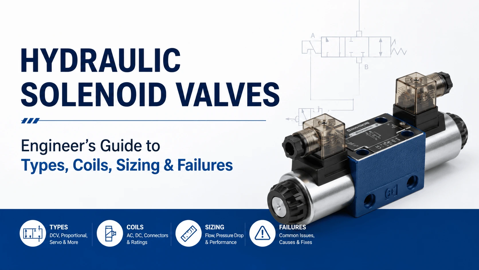
Hydraulic Solenoid Valves- Engineer's Guide to Types, Coils, Sizing & Failures

Table of Contents

Introduction

Every hydraulic system that runs on a PLC owes its automation to one small, cheap part: a hydraulic solenoid valve. A directional valve only shifts when something pushes its spool, and in most industrial and mobile systems, that something is an electromagnet the size of your thumb.

The concept is simple. Current flows through a coil, the coil makes a magnetic field, and the field yanks a plunger into the coil. That plunger pushes the spool. Hydraulic fluid then routes to the cylinder or motor you want to move.

The execution is harder than the concept suggests. Coil voltage, duty cycle, pull-in current, spool overlap, and contamination all decide whether your valve shifts in 12 ms or 60 ms, and whether the coil lasts ten years or ten weeks. This guide covers how solenoid valves work, how to size them, and how to keep them alive.

What is a Hydraulic Solenoid Valve?

A hydraulic solenoid valve is a directional control valve that an electrical solenoid actuates. The solenoid converts an electrical signal into mechanical force, and that force shifts the valve spool to route fluid between ports.
 
Most solenoid valves sit between the pump and the actuator. When you energize the coil, the spool moves and opens a path from the pressure line (P) to one work port (A or B), while the return line (T) drains the opposite work port. De-energize the coil, and a return spring snaps the spool back to its neutral position.
 
That is the whole job: route fluid on command. The engineering decisions start when you pick the configuration, the coil type, and the spool code for your circuit. Get those wrong and you get sluggish shifts, burnt coils, or a press that creeps when it should hold.

How a Solenoid Valve Works

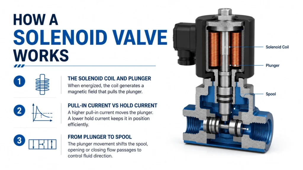
How a Solenoid Valve Works

The solenoid coil and plunger

The solenoid is a coil of copper wire wound around a bobbin, with a hollow tube down the middle. Inside that tube sits a ferromagnetic plunger (also called an armature). When you apply voltage, current builds in the coil and generates a magnetic field. The field pulls the plunger into the coil against a return spring.
 
The plunger connects to the spool through a push pin. As the plunger moves, it pushes the spool across the valve body. Cut the current, and the return spring pushes everything back. The stroke is short, usually 2 to 5 mm, but the force is high enough to move a spool against full system pressure.

Pull-in current vs hold current

Here is the detail most catalogs skip. A solenoid needs more current to pull the plunger in than it needs to hold it there. At the start of the stroke, the air gap between plunger and pole is large, so the magnetic force is low, and the coil must draw peak current, called pull-in or inrush current.
 
Once the plunger seats, the gap closes, the magnetic force rises sharply, and the coil can hold the plunger with a fraction of the inrush current. A standard DC solenoid draws its full rated current continuously once energized, which is why coil temperature climbs fast and duty cycle matters.
 
Some valves use economy circuits that drop current to a lower hold level after the plunger seats. This cuts heat, extends coil life, and lets you run a smaller power supply. If your valve runs more than 50 percent of the time, ask whether an economy coil is an option.

From plunger to spool

The plunger’s job ends at the spool. Once the spool shifts, porting inside the valve body takes over. A 4/3 valve, for example, has five lands on the spool and three positions. The lands uncover or block internal passages to connect P, T, A, and B in the pattern your circuit needs.
 
The spool-to-bore clearance is tight, typically 3 to 8 micrometers. That clearance lets a thin oil film lubricate the spool but also sets the internal leakage. A worn spool or contaminated oil widens that clearance, and leaks pressure away even when the valve sits in neutral.

Wet Pin vs Dry Pin Solenoids

This split shapes more buying decisions than almost any other spec. The “pin” is the push rod that transfers force from plunger to spool, and “wet” or “dry” tells you whether the plunger runs in oil or in air.

Dry pin solenoids

In a dry-pin design, the plunger runs in a sealed, air-filled tube. The push pin passes through a seal into the valve body. The plunger never touches hydraulic oil.
Dry-pin solenoids run hotter than wet-pin types because air cools worse than oil. They also wear faster because the plunger slides against a dry guide. The advantage is isolation: a torn seal on a dry-pin solenoid leaks air, not oil, so a failed coil does not contaminate the solenoid compartment.

Wet pin solenoids

In a wet-pin design, the plunger tube connects to the valve’s pressure gallery. System oil fills the tube and bathes the plunger. The push pin needs no dynamic seal against the spool because oil already surrounds it.
 
Wet-pin solenoids run cooler and quieter. The oil dampens plunger impact, which removes the sharp “click” you hear on dry-pin valves, and it lubricates the sliding surfaces. The trade-off is leakage: a small amount of oil always bleeds past the plunger into the spring chamber and back to tank. Most engineers accept that trade-off because wet-pin coils last longer and run quieter.
Characteristic Dry pin solenoid Wet pin solenoid
Plunger environment
Sealed air
Bathed in system oil
Cooling
Poor (air)
Good (oil)
Noise
Loud click
Quiet, damped
Seal requirement
Dynamic push-pin seal
None on plunger
Leakage
None past plunger
Small bleed to tank
Typical life
Shorter
Longer
Common use
Cost-sensitive, clean-oil systems
Most industrial and mobile valves

AC vs DC Solenoid Coils

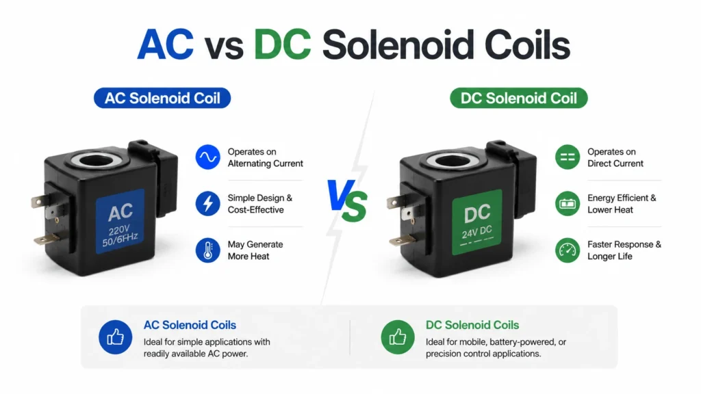
AC vs DC Solenoid Coils
Coil voltage choice has real consequences for reliability, not just for the power supply. AC and DC solenoids behave differently under fault, and the wrong choice will burn coils.

AC solenoids

An AC solenoid’s current depends on its inductance, and inductance depends on plunger position. When the plunger is out, inductance is low and current is high. When the plunger seats, inductance rises and current drops. That means an AC solenoid draws a large inrush current for the few milliseconds it takes to pull in, then settles to a low hold current.
 
This gives AC solenoids a fast, powerful pull. The danger is the failure mode. If the plunger sticks and never seats, the coil stays at inrush current. Within seconds, the coil overheats and burns out. Low line voltage causes the same problem: the plunger pulls in slowly, sits at high current longer, and the coil cooks.

DC solenoids

A DC solenoid’s current is set by coil resistance alone, so it draws the same current whether the plunger is in or out. That makes DC solenoids far more forgiving. A stuck plunger does not spike the current. Low voltage simply means a slower, weaker shift, not a burnt coil.
 
DC coils also survive long energized periods better, which matters for valves that hold position for minutes at a time. The downside is heat. A standard DC coil at full current runs hot because it cannot exploit the inductance drop that cools an AC coil after pull-in. Economy circuits solve this, but they add cost.
Characteristic AC solenoid DC solenoid
Current vs plunger position
High inrush, low hold
Constant
Pull force
High and fast
Lower, steady
Failure on stuck plunger
Coil burns out
Coil survives
Behavior on low voltage
Slow shift, coil overheats
Slow shift, no damage
Heat at hold
Low
Higher
Best for
Frequent switching, clean operation
Long hold times, harsh conditions
Most modern systems run DC solenoids, often 24 V DC, because PLC outputs and solid-state relays prefer DC. AC solenoids still appear on older machines and where a plant already distributes 110 V or 230 V control power.

Solenoid Valve Configurations

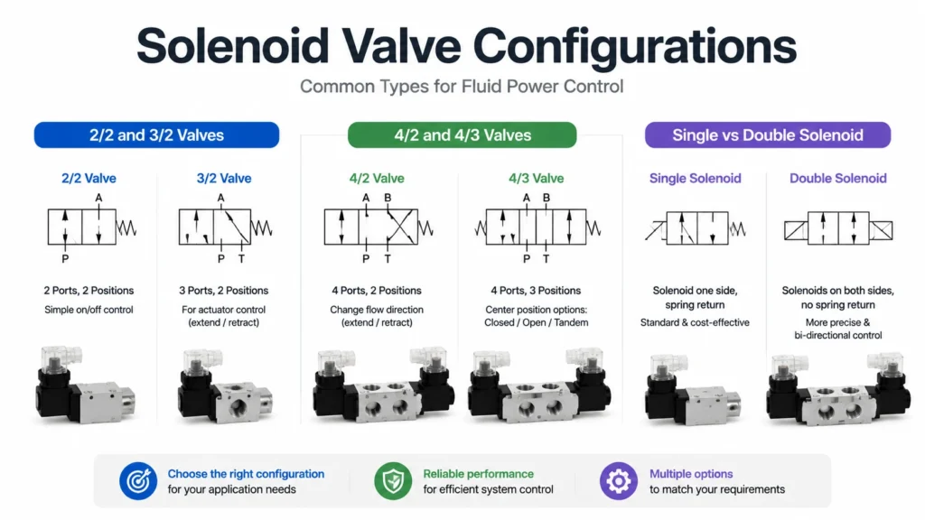
Solenoid Valve Configurations

2/2 and 3/2 valves

A 2/2 valve has two ports and two positions. It is a simple on/off switch for a single line. You see these in pilot circuits, drain lines, and bleed-off paths.
A 3/2 valve adds a third port, usually a return-to-tank path, and has three positions. The classic use is a single-acting cylinder. Energize the solenoid, and pressure extends the rod. De-energize, and the spring returns the rod while oil drains to the tank.

4/2 and 4/3 valves

A 4/2 valve has four ports (P, T, A, B) and two positions. It routes pressure to one work port while draining the other. Energizing the single solenoid flips the routing. There is no neutral, so the valve always drives the actuator one way or the other.
 
A 4/3 valve adds a center position. That center is where the engineering happens. A closed-center 4/3 blocks all four ports in neutral, which holds the load but deadheads the pump unless you run a relief or unload circuit. An open-center 4/3 connects P to T in neutral, which unloads the pump but lets the load drift. A tandem center connects A and B to T while blocking P, which holds the load and unloads the pump at the same time.

Single vs double solenoid

A single-solenoid valve uses one coil and one return spring. The spring holds neutral. Energize the coil and the spool shifts; release it, and the spring returns the spool. This is cheap and failsafe, because a power loss returns the valve to a known state.
A double-solenoid valve uses two coils and no centering spring (most models). Energize coil A, and the spool goes one way; energize coil B, and it goes the other. The valve holds its last position when both coils drop, which makes double-solenoid valves useful for holding a load without constant power.
The rule is simple. If your circuit needs a defined fail state, use a single solenoid. If you need to hold a position on command in either direction, use a double-solenoid and wire a manual override for safety.

Spool Types and Center Positions

The spool code tells you what the valve does in the center position, and it matters more than most buyers realize. The wrong code gives you a press that drifts or a pump that deadheads.
Spool code (center) P T A B Typical use
Closed (all blocked)
Blocked
Blocked
Blocked
Blocked
Hold load, deadhead pump
Open (P to T, A-B-T)
T
T
T
T
Free cylinder, pump unloaded
Tandem (P to T, A and B blocked)
T
T
Blocked
Blocked
Hold load, unload pump
Float (A-B-T, P blocked)
Blocked
T
T
T
Run motor to stop, pump held
Spool overlap is the other variable. Positive overlap means the spool covers a port slightly past center, which gives a brief “all ports blocked” state during shifting. That reduces leakage but adds a tiny dead time. Zero or negative overlap opens ports before the spool fully crosses center, which gives faster response but more crossover leakage.

Solenoid Valve Comparison Table

Configuration Ports / positions Solenoids Fail behavior Common application
2/2
2 / 2
1
Closes
Pilot supply, drain shutoff
3/2
3 / 2
1
Spring return
Single-acting cylinder
4/2
4 / 2
1
Spring return
Simple cylinder extend/retract
4/3 single
4 / 3
1
Spring to center
Hold-and-unload circuits
4/3 double
4 / 3
2
Holds last position
Bidirectional hold, press circuits
4/3 double, closed center
4 / 3
2
Holds load
Machine tools, clamps

Key Specifications and What They Mean

Rated flow and pressure

Rated flow is the flow that passes through the valve at a defined pressure drop, usually 5 bar or 10 bar, with the spool fully shifted. A CETOP NG6 valve typically handles 40 to 80 L/min at 5 bar drop. A CETOP NG10 valve moves 160 to 400 L/min at the same drop. If you push more flow than rated, the pressure drop climbs and the spool may not stay put.
Rated pressure is the maximum system pressure the valve body and seals tolerate. Most industrial solenoid valves run at 210 to 350 bar. Mobile valves often reach 350 to 420 bar. Always check the burst pressure, not just the rated pressure, if your system sees pressure spikes.

Response time

Response time is the delay between energizing the coil and the spool reaching its shifted position. Typical values run 10 to 50 ms for DC solenoids and 8 to 30 ms for AC solenoids. Faster is not always better. A 10 ms shift on a high-flow line causes a pressure spike that a 40 ms shift would avoid.
Response time grows with flow (flow forces fight the solenoid), drops with voltage (a low coil runs weaker and slower), and worsens with cold oil (high viscosity resists spool motion). If your spec sheet quotes a single number, ask what flow and oil temperature produced it.

Duty cycle

Duty cycle is the fraction of time a coil can stay energized without overheating. Continuous duty (100 percent or S1) means the coil can stay on indefinitely. Intermittent duty ratings like 50 percent or 30 percent mean the coil must rest to cool. Running an intermittent-duty coil continuously burns it out.
Most industrial solenoid valves now ship as continuous duty. Intermittent-duty coils still appear on cheap imports and on valves built for high inrush force. Read the rating before you wire the valve to a circuit that holds it on for minutes.

Coil voltage and power

Common coil voltages are 12 V DC, 24 V DC, 48 V DC, 110 V AC, 230 V AC, and 400 V AC. Mobile equipment almost always runs 12 V or 24 V DC. Industrial lines run 24 V DC for safety and PLC compatibility, with AC options on legacy panels.
Coil power ranges from 10 W on a small wet-pin DC solenoid to 50 W on a large AC coil. That power sets the heat load on your control cabinet and the current your relay or PLC output must switch. A 24 V DC coil at 25 W draws just over 1 A. A PLC output rated for 0.5 A cannot drive it directly, so you need an interposing relay.

Sizing a Solenoid Valve

Sizing starts with flow, not with ports. Calculate the flow your actuator needs at its working speed, then pick a valve size whose rated flow covers that with a margin.
For a cylinder, flow equals piston area times speed. A 100 mm bore cylinder extending at 100 mm/s needs about 47 L/min on the cap end. Pick a valve rated for at least 60 L/min at a 5 bar drop so you keep pressure loss low and headroom for flow spikes.
 
Check the pressure drop next. Every valve has a flow-vs-pressure-drop curve. At 80 L/min, a CETOP NG6 valve might drop 12 bar. That drop is wasted energy and heat. If the drop is too high, step up to NG10. If the drop is tiny, you may be overspending on a valve bigger than you need.
 
Finally, verify the coil can shift the spool against your worst-case pressure. Most catalogs quote a maximum operating pressure at which the solenoid still shifts. If your system spikes above that, the valve will stall in mid-shift, and the coil will overheat.

Mounting Standards and Porting

Solenoid directional valves follow standard mounting patterns, so you can swap brands. The two families that matter are ISO 4401 (also called CETOP) and, for cartridge valves, ISO 7368.
Standard Size Typical flow (L/min) Bolt pattern
ISO 4401 / CETOP NG6
NG6
40–80
4-bolt subplate
ISO 4401 / CETOP NG10
NG10
160–400
4-bolt subplate
ISO 4401 / CETOP NG16
NG16
400–800
4-bolt subplate
ISO 4401 / CETOP NG25
NG25
800–1500
4-bolt subplate
ISO 7368
Cartridge
Up to 1000+
Threaded cavity
Port threads usually follow SAE J1926 (straight thread O-ring) or ISO 6149 (metric straight thread with O-ring). Do not mix them. An SAE port and an ISO 6149 port look similar but the O-ring seat differs, and a cross-threaded fitting will leak.

Oil Cleanliness Requirements

Solenoid valves are more contamination-tolerant than proportional or servo valves, but they are not immune. The spool-to-bore clearance is only a few micrometers. A hard particle the size of a red blood cell can jam the spool.
Target ISO 4406 cleanliness of 21/19/16 for standard solenoid valves, and 19/17/14 for valves on high-pressure or critical circuits. That means your filters should catch particles above 10 micrometers with reasonable efficiency, and you should sample oil regularly.
 
Symptoms of contamination-driven failure include sluggish shifting, failure to reach the shifted position, and a coil that overheats because the plunger never seats. If you see those symptoms and your oil is dirty, fix the oil before you replace the valve. A new valve in dirty oil fails the same way.

Common Solenoid Valve Failures

Burnt coil

The most common failure. Causes include low voltage that keeps the plunger at high current, a stuck spool that never lets the AC coil drop to hold current, a shorted coil winding, or a duty-cycle violation. DC coils usually survive stuck spools; AC coils do not.

Sluggish or failed shift

A contaminated spool, cold oil, low voltage, or a weak return spring all slow the shift. The valve may shift partway and stall, which overheats the coil. Measure voltage at the coil terminals under load, not at the panel. Voltage drop across a long, thin wire can starve a 24 V coil down to 18 V.

Solenoid chatter

Chatter is rapid, partial shifting. It sounds like a buzz, and it destroys coils and spools fast. Causes include a weak control signal that flickers, a coil running on half-wave rectified DC, or a mechanical bind that makes the plunger bounce. Find the source before the valve welds itself open.

External leakage

Leakage past the solenoid tube seal or the subplate gasket wastes oil and lets dirt in. Tighten to spec, not harder. An over-torqued bolt warps the valve body and creates internal leaks that no seal can fix.

Troubleshooting Guide

Symptom Likely cause First check
Coil does not energize
No voltage, broken wire
Measure voltage at coil terminals under load
Coil energizes, no shift
Stuck spool, low voltage, cold oil
Check oil temp, measure voltage, inspect spool
Coil burns out (AC)
Stuck plunger, low voltage
Verify plunger moves freely, check line voltage
Slow shift
Cold oil, contamination, weak spring
Check ISO 4406, warm oil, measure response time
Chatter
Flickering signal, half-wave DC
Inspect signal with scope, replace rectifier
Drift in neutral
Worn spool, wrong center code
Confirm spool code, measure internal leakage
External leak
Loose bolts, bad seal
Retorque to spec, replace gasket, do not overtighten

How to Select the Right Solenoid Valve

Start with the circuit requirement. Decide whether you need a 2/2, 3/2, 4/2, or 4/3 valve, and pick the spool center code based on whether the load must hold or float in neutral.
Then the size of the flow. Calculate actuator flow at working speed, add a 20 percent margin, and match to a valve rated flow. Cross-check the pressure drop curve at your operating flow.
Pick the coil next. Match the voltage to your control power. Choose DC unless you have a specific reason for AC. Pick a wet-pin for cooler, quieter, longer life; pick a dry-pin only if isolation from oil matters.
 
Add the options your circuit needs. Manual override lets you shift the valve by hand for setup or fault-finding. Explosion-proof coils suit hazardous areas. LED indicators and surge suppressors protect your PLC outputs. Position sensors confirm the spool actually shifted.
 
Finally, match the mounting. Confirm the subplate pattern (ISO 4401 NG6, NG10, etc.) and port thread (SAE J1926 or ISO 6149) against your manifold. A valve that fits the cavity but not the thread is a return waiting to happen.
 

Maintenance Best Practices

Keep oil clean. Change filters on schedule, sample oil for ISO 4406 code, and flush new systems before first start. Contamination causes more solenoid failures than any other single factor.
Measure voltage at the coil under load. A 24 V coil that sees 18 V under load will shift slowly and run hot. If the voltage drops, fix the wiring or the power supply before the coil fails.
 
Replace coils in pairs on double-solenoid valves if one burns. The second coil ran the same hours under the same conditions, and a mismatched pull strength will shift the spool off-center.
Use the manual override during commissioning. It confirms the spool moves freely before you trust the electrical signal, and it isolates electrical from mechanical faults in minutes.
Keep spare coils and subplate gaskets on the shelf. A failed solenoid takes a machine down, and waiting on a part costs more than stocking it.
 

Industrial Applications

Solenoid valves run the on/off logic of almost every hydraulic machine. In construction equipment, they pilot the main directional valves on excavators and loaders. In agricultural machinery, they control implement raise, lower, and tilt functions.
 
In manufacturing presses, double-solenoid 4/3 valves hold and release clamps, sequence tool motions, and control press ram direction. Material handling uses them on conveyor diverters and lift gates. Marine hydraulics use solenoid valves for steering and winch control, often in 24 V DC versions for boat electrical systems.
 
Oil and gas applications demand explosion-proof coils and stainless hardware. Wind energy pitch systems use solenoid valves in failsafe circuits that return blades to a safe position on power loss. Anywhere a hydraulic actuator needs to move, stop, or hold on an electrical command, a solenoid valve is doing the work.


 FAQ

What is a hydraulic solenoid valve?

A hydraulic solenoid valve is a directional control valve that is shifted by an electrical solenoid. The solenoid coil converts current into a magnetic force, which pulls a plunger that pushes the valve spool. This route hydraulic fluid between the pressure, tank, and work ports to control a cylinder or motor.
 

How does a solenoid valve work in a hydraulic system?

Current flows through the solenoid coil, creating a magnetic field that pulls a ferromagnetic plunger into the coil. The plunger pushes the spool across the valve body, opening and closing internal passages that route fluid. Cut the current, and a return spring pushes the spool back to neutral.
 

What is the difference between wet pin and dry pin solenoids?

In a wet-pin solenoid, system oil bathes the plunger, which cools it, lubricates it, and dampens noise. In a dry-pin solenoid, the plunger runs in a sealed air-filled tube, so it runs hotter and louder but isolates the coil from oil. Wet-pin types last longer and run quieter; dry-pin types suit isolation-critical setups.
 

What voltage should I choose for a hydraulic solenoid valve?

Choose 24 V DC for most industrial and mobile systems because PLCs and solid-state relays handle DC well, and DC coils survive stuck spools without burning out. Use 12 V DC on battery-powered mobile equipment. Reserve AC coils for legacy panels that already distribute 110 V or 230 V control power.
 

Why do hydraulic solenoid coils burn out?

AC coils burn out when the plunger sticks and never seats, because the coil stays at high inrush current instead of dropping to low hold current. Low line voltage causes the same problem by slowing the pull-in. DC coils survive stuck plungers but burn from duty-cycle violations, shorted windings, or chronic undervoltage that overheats the coil.
 

How fast does a hydraulic solenoid valve shift?

Typical response time is 10 to 50 milliseconds for DC solenoids and 8 to 30 milliseconds for AC solenoids. Faster shifts cost more pressure spikes. Cold oil, low voltage, and high flow forces all slow the shift. Always confirm the test conditions behind a quoted response time.
 

What is the difference between 4/2 and 4/3 solenoid valves?

A 4/2 valve has four ports and two positions, with no neutral, so it always drives the actuator one way or the other. A 4/3 valve adds a center position that can hold the load (closed center), unload the pump (open or tandem center), or let the actuator float (float center). Choose 4/3 when your circuit needs a defined rest state.
 

Conclusion

The hydraulic solenoid valve is the cheapest, smallest, and most common actuator interface in fluid power. Get the basics right and it runs for years. Pick the wrong configuration, starve the coil of voltage, or run dirty oil, and it fails in weeks.
The decisions that matter are the ones this guide covers: wet-pin versus dry-pin, AC versus DC, the spool center code, the flow sizing, and the cleanliness target. Nail those and the rest is wiring and plumbing. Get them wrong, and no amount of premium branding will save the valve.
If you are specifying a solenoid valve for a new manifold or replacing one that keeps failing, the engineering team can help you match the configuration, coil, and mounting to your circuit before you buy.
 

Related Articles

Scroll to Top
Shoot Us An Email

Professional Manufacturer