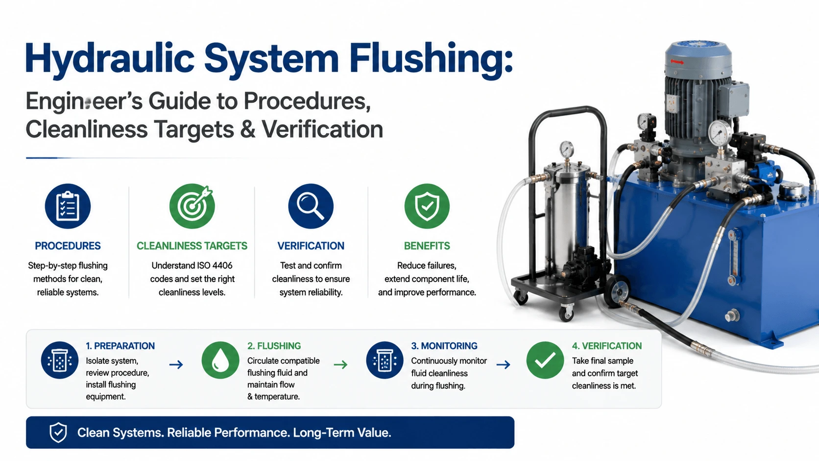
Hydraulic System Flushing: Engineer’s Guide to Procedures, Cleanliness Targets & Verification

Hydraulic System Flushing- Engineer's Guide to Procedures, Cleanliness Targets & Verification

Table of Contents

What is Hydraulic System Flushing?

Hydraulic system flushing is the controlled circulation of fluid through a hydraulic circuit at specified velocities and temperatures. Its purpose is to dislodge, suspend, and remove construction debris, machining particles, weld slag, mill scale, rust, and any other solid contaminants introduced during fabrication, assembly, or repair. A properly executed flush reduces the particle concentration in the system fluid to a level compatible with the most sensitive components installed in the circuit.
 
The keyword here is controlled. Simply filling the reservoir, starting the pump, and moving cylinders back and forth for an hour is not flushing. That is wishful thinking with a price tag attached. Effective flushing demands attention to flow velocity, fluid temperature, valve cycling, filtration capacity, and verification method. Skip any of these variables, and you leave contaminants in places that cause trouble later.
 
The physics behind flushing is straightforward. Particles adhere to internal surfaces through static friction, van der Waals forces, and surface tension from residual oils. To dislodge them, the flowing fluid must exert sufficient shear stress at the boundary layer. Higher Reynolds numbers (turbulent flow) create more effective scouring than laminar flow at the same volumetric rate. Thermal expansion and contraction loosen particles embedded in surface irregularities.
 
Rapid pressure changes and direction reverses generate inertial forces that shake loose debris from dead legs and valve cavities. A good flush exploits all these mechanisms systematically.

When to Flush: Four Triggers That Should Never Be Ignored

New System Commissioning

Every new hydraulic system needs a flush before it goes into service. No exceptions. New tubing carries mill scale from the drawing process. Welded joints leave slag and an undercut. Cut ports produce burrs. Hoses shed rubber and fabric particles during the first flex cycles. Fittings introduce thread chips and assembly lubricant residue.
 
Even components delivered “clean” from the factory have shipping preservative coatings and handling contaminants that must be removed. I have yet to see a new hydraulic system arrive clean enough to skip a flush. The ones that try are the ones calling me three months later about premature filter clogging and sticky valves.

After Major Component Replacement

Replacing a main pump, a large directional valve bank, or a set of cylinders exposes the open circuit to environmental contamination. Even with careful blanking, dust and particulate enter the system during the work window.
 
The replacement process also generates its own debris: cutting old fittings, grinding welds, re-tapping ports, and scraping old seal material from housings.Any time you crack open a major section of the hydraulic circuit, plan a flush as part of recommissioning. The cost of a half-day flush is trivial compared to the cost of destroying a new pump in its first week.

Before Fluid Change or Viscosity Upgrade

When changing from one hydraulic fluid to another, especially across viscosity grades or from mineral to synthetic base stocks, a flush removes residual old fluid that would otherwise dilute or contaminate the new charge. This matters more than most people realize. A 10% residual carryover of degraded, oxidized oil can cut the new fluid’s service life by 30% or more.
 
It also introduces acid number elevation, depleted additive packages, and suspended wear metals directly into the fresh fill. If you are upgrading to a higher-performance fluid, do not let the old fluid sabotage the investment.

After Catastrophic Failure

A pump seizure, a hose burst under load, or a catastrophic bearing failure injects massive quantities of metallic debris into the system. The fluid turns black with wear particles. Filters plug solid in minutes. In this scenario, a simple drain-and-refill is nowhere near sufficient.
 
The system requires a thorough disassembly inspection, component cleaning or replacement, and a multi-stage flush before any new parts go in. I have seen plants skip this step after a major failure, then wonder why the replacement pump failed within 50 hours. The answer: metal fines from the previous catastrophe sat in every corner of the circuit, waiting for their next victim.

Pre-Flush Preparation: The Step Most Procedures Skip

Before circulating a single liter of flush fluid, spend time on preparation. This phase determines whether the flush succeeds or merely circulates contaminants through areas they were never meant to reach.

Blank Off or Remove Sensitive Components

Servo and proportional valves, high-response actuators, and precision flow controls cannot tolerate the debris loading that occurs during a flush. Remove these components from the circuit and install jump lines or spool pieces in their place.
 
If removal is impractical, install temporary bypass lines around the critical assembly and isolate it with ball valves. Never run flush fluid through a servo valve unless you have budgeted for its replacement.

Install Temporary Filtration

The system’s permanent filters will plug within minutes during an aggressive flush. Plan for this by installing high-capacity temporary filter housings in the return line and, if possible, the pressure line. Use coarse beta-rated elements (beta-10 or beta-20 at 10 microns) for the initial flush stages, then swap to finer media (beta-1000 at 3 microns) as particle loading drops. Monitor differential pressure across the temporary filters and change elements before they go into bypass mode.

Remove Flow Restrictions

Sharp-edged orifice plates, flow restrictors, and small-diameter pilot lines create localized high-velocity jets that erode temporary debris into finer, more harmful particles. Remove or bypass these restrictions during the flush. Replace them with straight spool pieces and reinstall the original hardware only after final cleanliness verification passes.

Clean or Replace Reservoir

Drain the reservoir completely. Wipe down interior surfaces with lint-free cloths. If the reservoir has visible rust, scale, or sludge accumulation, consider a professional cleaning or liner replacement. For new systems, vacuum out any loose debris left from fabrication. Do not rely on the flush fluid to clean the reservoir; it is there to clean the circuit, not the tank itself.

Verify Flush Cart or Auxiliary Pump Capacity

The flush pump must deliver sufficient flow to achieve the target Reynolds number in the largest-diameter lines. As a rule of thumb, turbulent flow in hydraulic tubing begins at approximately Reynolds number 4000. For a given tube ID, calculate the minimum flow required using:
Re = (rho x v x D) / mu
where rho is fluid density (kg/m3), v is mean velocity (m/s), D is tube inner diameter (m), and mu is dynamic viscosity (Pa.s). Most flush procedures target 2 to 3 times the minimum turbulent flow velocity in order to ensure adequate shear stress throughout the boundary layer.
 
If your auxiliary flush pump cannot achieve turbulent flow in the larger lines, accept that your flush will be less effective in those sections and plan additional measures such as mechanical agitation, thermal cycling, or extended duration to compensate.

Low-Pressure Flushing vs High-Velocity Flushing: Choosing the Right Method

Not all flushes require the same approach. The choice between low-pressure (laminar or transitional) flushing and high-velocity (turbulent) flushing depends on the condition of the system, the target cleanliness, and the sensitivity of the components that will eventually operate in the circuit.

Low-Pressure Flushing (Break-In Mode)

Low-pressure flushing operates at relatively modest flow rates, typically below the turbulent threshold for the majority of the piping. Pressures range from 5 to 15 bar, and fluid velocities stay in the 0.5 to 1.5 m/s range for standard tubing sizes. The goal here is gentle removal of loose debris without generating excessive heat or stressing temporary connections.
 
This mode suits systems that are already reasonably clean: post-repair flushes on well-maintained circuits, pre-fluid-change rinses, and situations where high-velocity flow would overload temporary filtration or exceed the rating of jump lines and hoses. Low-pressure flushing also serves as the initial stage of a multi-phase flush program, running for the first several system volumes to capture the bulk of loose contaminants before ramping up to turbulent flow.

High-Velocity Flushing (Turbulent Scouring)

High-velocity flushing deliberately operates above the turbulent transition point, targeting Reynolds numbers of 8000 to 15000 in critical lines. Fluid velocities commonly reach 3 to 8 m/s, depending on line diameter and fluid properties. Pressure fluctuations from turbulence and intentional valve cycling create the dynamic forces needed to dislodge adhered particles from tube walls, fitting internals, and dead-end passages.
 
This is the method required for new system commissioning, post-catastrophic-failure cleanup, and any situation where mill scale, weld slag, or firmly attached deposits are present. It demands robust temporary plumbing, adequately sized filter housings, a pump with sufficient head, and careful monitoring of connection integrity. A blown hose at 15 m/s fluid velocity makes an impressive mess and a safety hazard. Secure every joint before opening the throttle.
Parameter Low-Pressure Flush High-Velocity Flush
Typical flow velocity
0.5 – 1.5 m/s
3 – 8 m/s
Reynolds number
< 4000 (laminar/transition)
8000 – 15000 (turbulent)
Operating pressure
5 – 15 bar
10 – 30 bar (fluctuating)
Primary mechanism
Suspension and transport of loose debris
Turbulent scour + inertial dislodgement
Filter loading rate
Moderate
High (plan frequent element changes)
Typical application
Post-repair, pre-fluid-change, initial break-in
New commissioning, post-catastrophic, heavy contamination
Duration
3 – 7 system volumes
10 – 20+ system volumes
Equipment demand
Standard portable filter cart
Dedicated flush pump, oversize temp filters

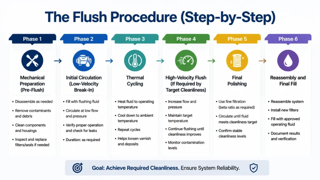
The Flush Procedure (Step-by-Step)

The Flush Procedure (Step-by-Step)

What follows is a field-ready procedure based on practices I have used in steel mills, marine, and manufacturing environments. Adapt the specific values to your system size, component mix, and cleanliness target, but keep the sequence intact.

Phase 1: Mechanical Preparation (Pre-Flush)

  1. Isolate the hydraulic system from all loads and actuators. Disconnect or block cylinder rods so they cannot extend under pressure.
  2. Remove or blank off all servo valves, proportional valves, and precision flow control devices. Document the location of each removed component.
  3. Install temporary jump lines or spool pieces in place of removed components. Use clean, flushed hose assemblies.
  4. Install temporary high-capacity filter housings in the return line and pressure line. Fit with coarse elements initially.
  5. Remove or bypass all fixed orifices, flow restrictors, and sharp-line restrictions. Record locations for reinstallation.
  6. Drain the reservoir completely. Clean interior surfaces manually. Inspect for scale, sludge, and corrosion.
  7. Refill the reservoir with flush fluid to the minimum operating level. Use filtered fluid at or better than the target cleanliness code.

Phase 2: Initial Circulation (Low-Velocity Break-In)

  1. Start the flush pump or auxiliary power unit at low speed. Verify flow in both directions for reversible circuits.
  2. Circulate fluid at low velocity (0.5 to 1.0 m/s) for 3 to 5 system volumes. One system volume equals the total fluid capacity of the entire hydraulic circuit, including lines, manifolds, cylinders, accumulators, and the reservoir.
  3. During initial circulation, activate all directional valves. Cycle each valve fully at a rate of one stroke every 5 to 10 seconds. Rapid direction changes generate pressure spikes that help dislodge debris from valve bodies and spool lands.
  4. Monitor the temporary filter differential pressure. Change elements when delta-P reaches 70% of the element bypass setting.
  5. Collect fluid samples at the end of Phase 2 for baseline particle count. Record ISO 4406 code.

Phase 3: Thermal Cycling

  1. Heat the flush fluid to 60 to 70 degrees C. Most mineral-based flush oils thin sufficiently at this range to promote turbulence at lower flow rates. Check that temporary hoses and seals are rated for the temperature.
  2. Hold at temperature for a minimum of 2 system volumes while maintaining valve cycling.
  3. Allow the system to cool to 30 to 35 degrees C. Thermal contraction helps crack loose particles embedded in surface irregularities.
  4. Repeat the heat-cool cycle at least 3 times. More cycles improve effectiveness on heavily scaled systems but yield diminishing returns after 5 to 6 cycles.
  5. Continue collecting fluid samples every 3 system volumes. Track particle count trend.

Phase 4: High-Velocity Flush (If Required by Target Cleanliness)

  1. Ramp the flush pump to achieve turbulent flow (Re > 8000) in the largest lines. Verify the calculated Reynolds number against the measured flow and temperature.
  2. Maintain turbulent circulation for 10 to 15 system volumes minimum. Systems with long runs of large-bore tubing may require up to 20 volumes.
  3. Intensify valve cycling. Target one full stroke per second on each directional valve where feasible. The repeated pressure transients are more valuable for cleaning than steady-state flow alone.
  4. Tap fittings and lines periodically with a brass hammer during high-velocity flow. Mechanical vibration dislodges particles that fluid shear alone cannot remove.
  5. Watch the filter differential pressure closely. Expect to change temporary elements frequently, possibly every 2 to 3 system volumes during aggressive phases.

Phase 5: Final Polishing

  1. Reduce flow to moderate velocity. Swap temporary filter elements to fine-grade media (beta-1000 at 3 microns equivalent).
  2. Circulate for an additional 3 to 5 system volumes with continuous fine filtration.
  3. Take final fluid samples from at least two points: the return line downstream of the last filter and the lowest point in the reservoir (where settleable particles accumulate).
  4. Send samples for particle count analysis. Compare results against the target ISO 4406 code for the most sensitive component in the system.

Phase 6: Reassembly and Final Fill

  1. Stop the flush pump. Drain all flush fluid from the system. Do not leave flush fluid in the circuit; it is now contaminated with the debris you just removed.
  2. Remove all temporary filter housings, jump lines, and spool pieces. Reinstall original components that were removed in Phase 1. Use clean assembly practices: lint-free gloves, wiped fittings, and new seals where applicable.
  3. Install new, factory-fresh filter elements in all permanent filter housings. Never reuse the elements from the flush; even if they look clean, their structural integrity and beta-rating are questionable after a heavy flush.
  4. Fill the system with the designated operating fluid. Filter the incoming fluid through a 3-micron absolute transfer cart at a minimum.
  5. Bleed air from high points. Cycle actuators slowly to purge trapped air from cylinders and lines.
  6. Perform a final particle count check after 1 to 2 hours of low-load operation at normal system pressure. Confirm cleanliness has been maintained through the reassembly process.

Flush Fluid Selection: Dedicated Flush Oil vs Operating Fluid

The question comes up on nearly every project: do we buy dedicated low-viscosity flush oil, or do we just cheap out and use our regular hydraulic oil? There is a legitimate case for each option, and the wrong choice costs money in different ways.

Dedicated Low-Viscosity Flush Oil

Dedicated flush oils are formulated specifically for flushing applications. They typically have viscosities in the ISO VG 10 to VG 32 range at 40 degrees C, significantly lower than most operating fluids (VG 32 to VG 68). Lower viscosity means lower pumping losses at high flow rates, better turbulence at a given pump output, improved penetration into narrow clearances, and enhanced particle suspension characteristics. Many flush oils also contain detergents and dispersants that help keep dislodged particles in suspension long enough for the filters to capture them.
 
The downside is cost. Flush oil is a consumable you will discard after use (or send for reclamation). On a large system with 2000 liters of volume requiring 15 turnovers, that is 30,000 liters of flush oil purchased, used once, and disposed of. And you still have to buy the actual operating fluid for the final fill.

Using Regular Hydraulic Oil as Flush Fluid

Using your standard operating fluid as the flush medium eliminates the fluid purchase and compatibility-risk concerns. Whatever ends up left in the system after draining is compatible with the final fill because it IS the final fill. This approach works well for smaller systems, post-repair flushes where contamination levels are modest, and situations where flush oil availability or disposal logistics are problematic.
 
However, standard hydraulic oil at VG 46 or VG 64 viscosity requires substantially more pump power to push through the circuit at turbulent velocities. At 50 degrees C, a VG 46 oil has roughly twice the dynamic viscosity of a VG 15 flush oil. Your flush pump may not achieve the target Reynolds number, which means reduced scouring effectiveness. You also consume your expensive operating fluid in a dirty process and must still account for its eventual loss or reconditioning.

Compatibility Warning

Never mix flush oil formulations indiscriminately. If you use a dedicated flush oil followed by a different operating fluid, verify chemical compatibility. Some flush oils contain solvents or detergent packages that are incompatible with certain seal materials (especially polyurethane and some nitrile formulations) or with anti-wear additive packages in the final fluid.
 
Always consult the fluid supplier’s technical data sheet and perform a compatibility test if the combination is unfamiliar. A swollen seal discovered during commissioning is an expensive lesson in chemistry.

ISO 4406 Cleanliness Targets by Component Sensitivity

How clean is clean enough? The answer depends entirely on what components you are protecting. A gear motor driving a conveyor tolerates far more particles than a servo valve positioning a steel mill roll gap. Set your target based on the most sensitive device in the circuit, not the average.
Component Type Recommended ISO 4406 Target (Post-Flush) Rationale
Gear pumps, gear motors, vane pumps
18/16/13 or cleaner
Tolerances 5-15 micron; moderate contamination sensitivity
Fixed-displacement piston pumps
17/15/12 or cleaner
Port plate clearances 3-10 micron; sensitive to silting
Variable-displacement piston pumps (standard)
16/14/11 or cleaner
Swash plate slipper clearance 1-5 micron
Servo valves and proportional valves (general industrial)
15/13/10 or cleaner
Spool land clearance 2-5 micron; null leakage critical
High-response servo valves (aerospace / simulators)
14/12/9 or cleaner
Critical-center spool, flapper-nozzle or jet-pipe pilot stage
Hydraulic cylinders (heavy-duty, sealed)
18/16/13 acceptable
Large clearances; rod seal is primary defense
Hydraulic cylinders (precision, low-friction seals)
16/14/11 or cleaner
Seal groove tolerance tighter; scoring risk
These targets apply to the fluid condition after the flush is complete and verified. They are not interim targets during the flush process itself. Expect particle counts during active flushing to be significantly worse than the final target; the whole point is that the flush mobilizes contaminants so the filters can remove them.
 
For reference, typical as-delivered cleanliness of a new, unflushed hydraulic system ranges from ISO 4406 22/20/18 to 24/22/20 or worse, depending on fabrication quality and storage conditions. Getting from 23/21/18 down to 16/14/11 is a reduction of roughly 98% in particles greater than 4 microns per milliliter. That takes real effort, not hope.

Verifying Flush Completeness: Particle Counters, Patch Tests, and Lab Analysis
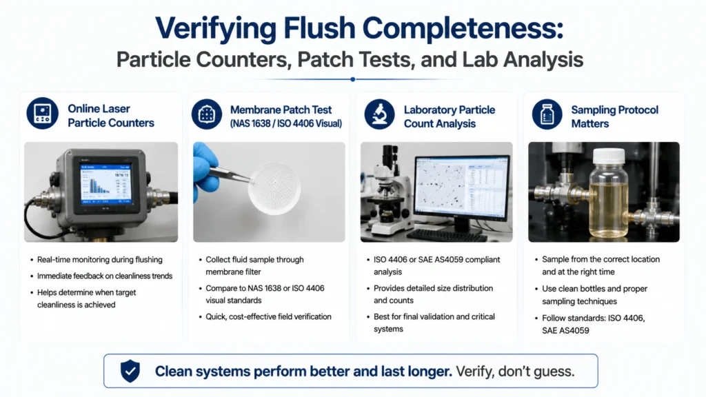
Verifying Flush Completeness- Particle Counters, Patch Tests, and Lab Analysis

You cannot manage what you do not measure. You cannot claim a flush is complete without data. Visual inspection, “the fluid looks clean,” is worthless for this purpose. The human eye cannot reliably detect particles below about 40 microns. The contaminants that kill hydraulic components are predominantly in the 3 to 20 micron range.

Online Laser Particle Counters

An inline laser particle counter mounted in the return line provides real-time feedback on fluid cleanliness during the flush. These instruments report ISO 4406 codes continuously and show trends as cleanliness improves. The ability to see particle counts drop in real time lets you make informed decisions about when to advance to the next phase or extend the current one. Good units offer multi-channel sizing (>4/>6/>14/>21 micron per ISO 4406) and data logging for traceability.

Cost is the main barrier. A decent online particle counter runs USD 8000 to 25000, depending on features and brand (Pall, Parker, Hydac, Vickers). For plants that commission multiple systems per year, the investment pays for itself quickly in reduced warranty claims and fewer repeat flushes. For smaller operations, rental units are available from many filter suppliers and service companies.

Membrane Patch Test (NAS 1638 / ISO 4406 Visual)

The patch test is the low-tech alternative. Pass a known volume of fluid, typically 100 mL, through a 0.8-micron or 1.2-micron analytical membrane filter under vacuum. The captured particles form a visible patch on the membrane. Compare this against standard contamination images, or grade it visually using the NAS 1638 scale (classes 00 through 8).

Patch tests cost almost nothing per sample and require minimal equipment: a vacuum pump, a filter holder, and a supply of membranes. They are subjective compared to laser counting, and they do not differentiate particle sizes precisely, but they catch gross contamination that would indicate an incomplete flush. Many experienced technicians can judge whether a system is approaching its target within 1 or 2 ISO codes just by looking at the patch.

Laboratory Particle Count Analysis

Sending fluid samples to an independent laboratory for automatic particle count (ISO 4406 per ISO 11500) provides documented, traceable certification of cleanliness. Labs use calibrated light-extinction or light-scattering instruments under controlled conditions. Results come with a formal report suitable for customer handover or quality-system records.

The drawback is turnaround time. Samples shipped to a lab may take 24 to 72 hours for results. By then, you have either moved forward and accepted the risk or sat idle waiting. Best practice is to combine methods: use an online particle counter or patch test for real-time decisions during the flush, then pull lab samples for final documentation.

Sampling Protocol Matters

A bad sample produces misleading results regardless of the analysis method. Follow these rules:

  • Draw samples from active, turbulent flow zones, never from stagnant reservoir corners or dead-ended lines.
  • Use clean, dedicated sampling bottles. Bottles pre-cleaned to ISO 4406 12/10/8 or better are available from labs and suppliers. Never reuse a bottle.
  • Purge the sampling valve for at least 200 to 500 mL before collecting the sample. The fluid in the valve body is not representative of system condition.
  • Cap the bottle immediately. Minimize exposure to atmospheric dust.
  • Label with date, time, system location, sample point, and operating conditions.
  • Analyze samples within 24 hours of collection if possible. Particle agglomeration and settling alter counts over extended storage.

Common Mistakes That Ruin a Good Flush
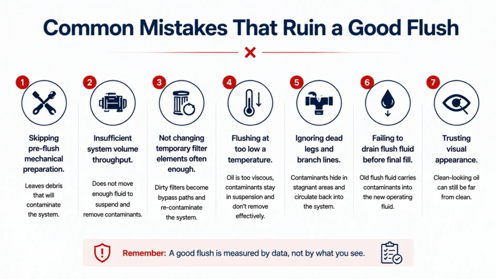
Common Mistakes That Ruin a Good Flush

I have seen more flushes fail from procedural errors than from equipment limitations. Here are the mistakes that show up repeatedly.
Skipping pre-flush mechanical preparation. Leaving servo valves in the circuit during a high-velocity flush is the single most expensive error I encounter. The flush debris destroys the servo valve’s tight spool clearances, and then the technician reinstalls a damaged component and wonders why the system hunts and drifts. Remove the sensitive parts first. Every time.
 
Insufficient system volume throughput. Running 3 system volumes and declaring victory is not adequate for anything beyond a light rinse. New systems with welded tubing commonly require 15 to 20 volumes to reach acceptable cleanliness. Track your cumulative volume and compare it against the target for your starting contamination level.
 
Not changing temporary filter elements often enough. Once a filter element reaches its terminal differential pressure and goes into bypass, it stops capturing particles. All subsequent circulation moves contaminants through the system without filtration. Monitor delta-P religiously and change elements before bypass. Keep a log of element changes with cumulative volume at each change; this record reveals a lot about the contamination profile of your system.
 
Flushing at too low a temperature. Cold viscous fluid does not achieve turbulent flow at realistic pump outputs, and it holds particles poorly in suspension. Get the fluid to 55 to 65 degrees C before expecting meaningful results. If your system lacks a built-in heater, use immersion heaters in the reservoir or recirculate through a heat exchanger.
 
Ignoring dead legs and branch lines. Main lines get clean because most of the flow travels through them. Branch lines to sensors, pilot circuits, drain lines, and accumulator charging paths often see minimal flow and retain contaminants long after the main loop is clean. Isolate and flush branch circuits individually, or ensure the flush procedure includes periodic full-system cycling that pushes fluid through every pathway.
 
Failing to drain flush fluid before final fill. Flush fluid is dirty fluid by design. Leaving even 5% residual flush oil in the system contaminates your fresh operating fill. Drain as completely as possible. On large systems, consider a low-viscosity intermediate rinse with the final-fill fluid before the final charge.
 
Trusting visual appearance. Clear-looking fluid can easily be ISO 4406 19/17/14 or worse. The particles that matter are invisible. Verify with instrumentation or patch testing every time. Visual checks are useful for detecting gross issues (water, severe discoloration, foam), but nothing more.
 

FAQ

What is hydraulic system flushing?

Hydraulic system flushing is the controlled circulation of fluid through a hydraulic circuit at specified flow velocities and temperatures. Its purpose is to remove construction debris, machining particles, weld slag, mill scale, and other solid contaminants. Unlike a simple drain-and-refill, a proper flush uses turbulent flow, thermal cycling, valve actuation, and high-capacity filtration. It actively dislodges, suspends, and captures contaminants that would otherwise remain in the system and damage sensitive components during operation.
 

When should you flush a hydraulic system?

Flush a hydraulic system in four situations:
(1) new system commissioning before any operational service;
(2) after major component replacement where the circuit was opened to the environment;
(3) before changing to a different hydraulic fluid type or viscosity grade; and
(4) after a catastrophic failure such as pump seizure or major hose burst that injected metallic debris throughout the circuit. Of these, new system commissioning is the most frequently overlooked and the most costly to skip.
 

What is the ISO 4406 target for a flushed hydraulic system?

The target depends on the most sensitive component in the system. Gear motors and vane pumps generally require ISO 4406 18/16/13 or cleaner. Variable displacement piston pumps need 16/14/11 or cleaner. Proportional and servo valves require 15/13/10 or cleaner. High-response aerospace-grade servo valves demand 14/12/9 or better. Set your target to the most stringent requirement among all installed components, not the average. A system is only as clean as its weakest link demands.
 

How do you verify that a flush is complete?

Verification requires instrumentation, not visual inspection. The three reliable methods are: (1) an inline laser particle counter providing real-time ISO 4406 readings during the flush; (2) a membrane patch test comparing captured contamination against standard images; and (3) laboratory particle count analysis per ISO 11500 for formal documentation. Combine methods where possible. Use real-time monitoring for operational decisions and lab samples for final certification. Always draw samples from active flow using clean bottles, and analyze within 24 hours of collection.
 

How many system volumes do you need to flush?

Volume requirements depend on the starting contamination level and the target cleanliness. A light post-repair rinse may reach acceptable levels in 3 to 5 system volumes. New system commissioning with welded tubing typically requires 15 to 20 volumes split across low-velocity break-in, thermal cycling, and high-velocity phases. Post-catastrophic-failure cleanup can exceed 25 volumes if heavy metallic loading is present. Track cumulative pumped volume against particle count trend rather than relying on arbitrary time-based targets.
 

What is high-velocity flushing versus low-velocity flushing?

High-velocity flushing operates above the turbulent transition (Reynolds number 8000 to 15000) at fluid velocities of 3 to 8 m/s. It uses turbulent shear and pressure fluctuations to scour firmly adhered debris from internal surfaces. This method is required for new systems, heavily contaminated circuits, and any situation involving mill scale or weld slag. Low-velocity flushing runs below the turbulent threshold (0.5 to 1.5 m/s). It suits post-repair rinses, pre-fluid-change cleaning, and initial break-in before ramping to high-velocity stages. Most thorough flush programs use both methods sequentially.
 

Can you use regular hydraulic oil as flush fluid?

Yes, for smaller systems and lighter contamination scenarios. Using the same fluid for flushing and final operation eliminates compatibility risks and simplifies logistics. However, standard hydraulic oil (typically VG 46 or VG 64) has higher viscosity than dedicated flush oils (VG 10 to VG 32). This means more pump power is needed to achieve turbulent flow, which reduces scouring effectiveness. Dedicated flush oils offer lower viscosity, better particle suspension, and often include detergents that aid cleaning. The trade-off is purchasing and disposing of a separate consumable fluid. Choose based on system size, target cleanliness, and available pump capacity.
 

Conclusion

A properly executed hydraulic system flushing is unglamorous, time-consuming, and absolutely necessary for any system you expect to run reliably. The procedure itself is not complicated. Prepare the circuit mechanically. Start gently. Add heat and direction changes. Ramp up velocity if the system needs it. Filter aggressively. Verify with real data.
The engineering judgment comes in knowing which method to apply and when you have done enough. Sometimes the numbers stop improving and you must investigate further before continuing.
 
Most of the flush failures I have seen came from skipping steps to save time, not from technical impossibility. The EUR 45,000 pump mentioned at the beginning died because nobody allocated two days for a flush that would have cost less than EUR 500 in consumables. That ratio shows up repeatedly in this business. Do the flush. Do it right. Document it. Your components will notice the difference.

Related Articles

Scroll to Top
Shoot Us An Email

Professional Manufacturer