Hydraulic Pressure Reducing Valve: the Ultimate Guide

Hydraulic Pressure Reducing Valve- Working Principle and Selection Guide

Table of Contents

Most hydraulic systems run at one pressure. Some machines need two. A clamp holds at 210 bar while a drill feeds at 140 bar. A press forms at 350 bar but returns at 70 bar. You cannot fix this mismatch with a relief valve alone. Relief valves limit maximum system pressure.
 
They do not reduce pressure in a branch circuit. That job falls to the hydraulic pressure reducing valve. This article covers how these valves work, which type to pick, and how to keep them running reliably.

What is a Hydraulic Pressure Reducing Valve?

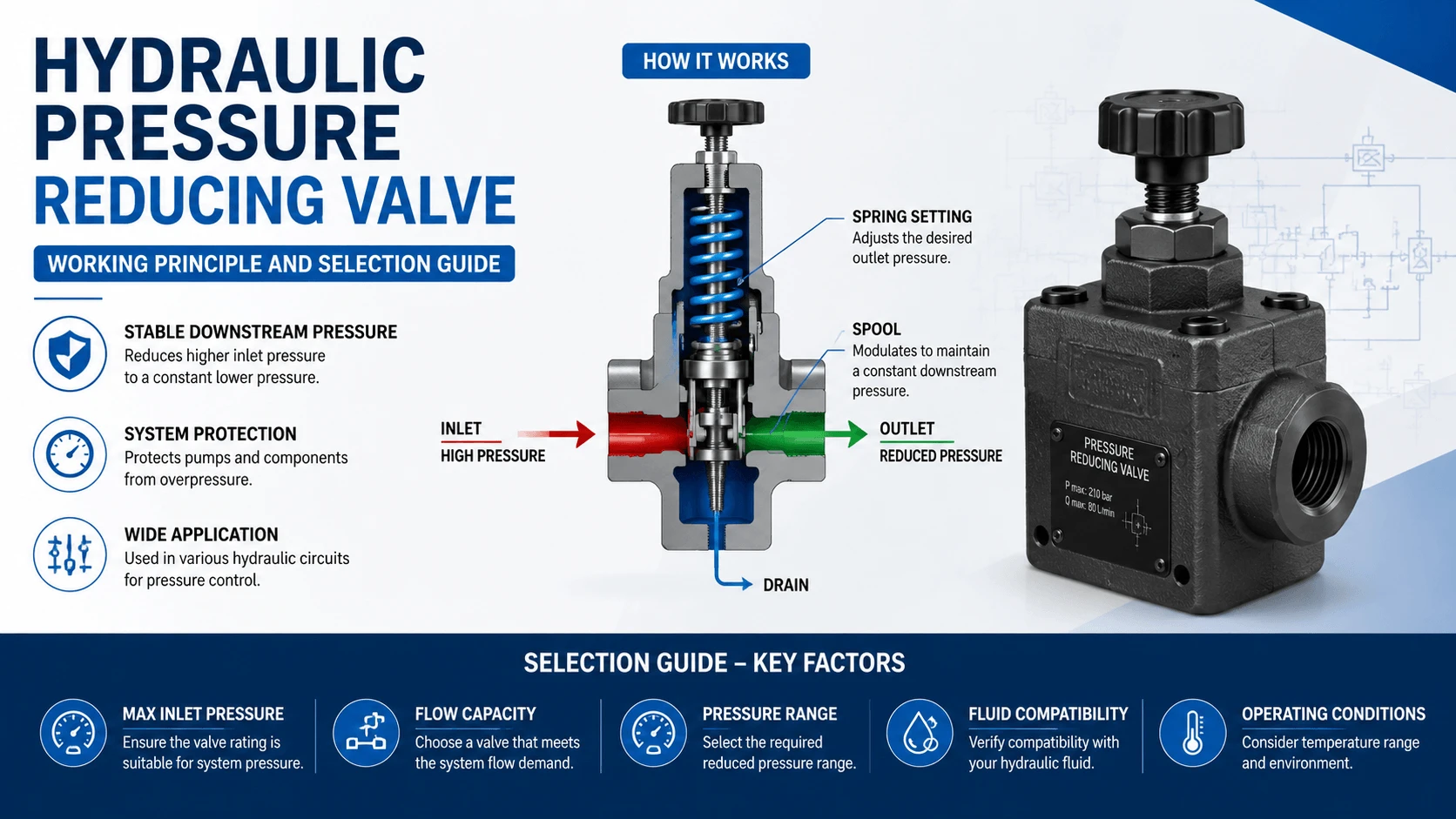
A hydraulic pressure reducing valve is a normally open pressure control valve. It maintains a constant lower pressure at its outlet regardless of higher inlet pressure. Fluid flows freely until the outlet pressure reaches the set point. Then the valve partially closes to create a pressure drop across the restriction.
 
Downstream equipment sees only the reduced pressure you set. The schematic symbol shows a normally-open valve with an external pilot line sensing outlet pressure and a spring setting the target value. An external drain line carries leaked oil to the tank. This drain connection matters. Block it, and the valve cannot regulate.

How It Works: Force Balance Inside the Valve
How It Works- Force Balance Inside the Valve
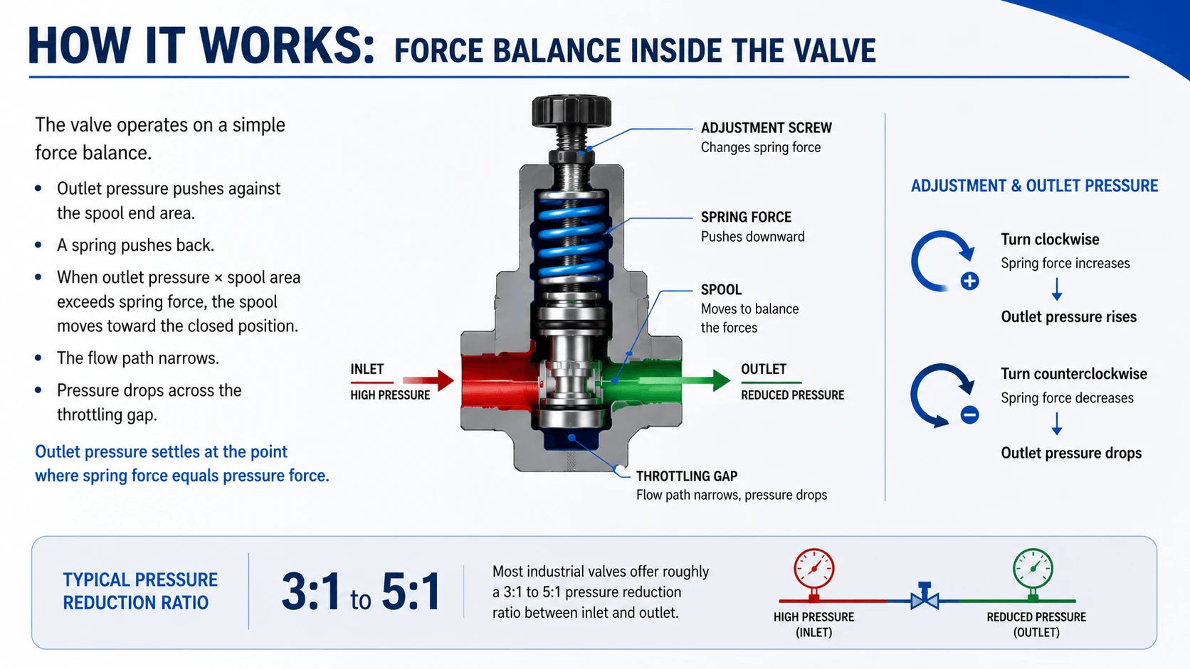
The valve operates on a simple force balance. Outlet pressure pushes against the spool end area. A spring pushes back. When outlet pressure times spool area exceeds spring force, the spool moves toward the closed position. The flow path narrows. Pressure drops across the throttling gap. Outlet pressure settles at the point where spring force equals pressure force.
 
In this type of valve, the spring sets the outlet pressure directly. Turn the adjustment screw clockwise, and the spring force increases. Outlet pressure rises. Turn it counterclockwise and the pressure drops. Most industrial valves offer roughly a 3:1 to 5:1 pressure reduction ratio between inlet and outlet.

Direct-Acting vs Pilot-Operated Designs
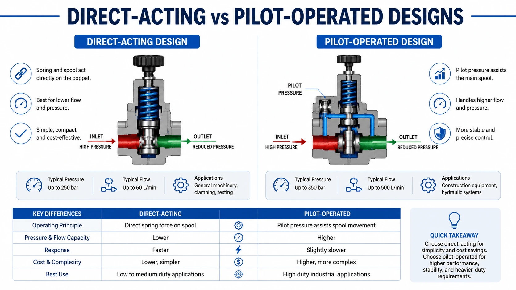
Direct-Acting vs Pilot-Operated Designs
Two basic designs exist. Each has strengths and limits.

Direct-Acting Pressure Reducing Valve

Direct-acting valves use a single spring and spool. Outlet pressure acts directly against the spring. Simple construction keeps cost low. Response is fast. But spring stiffness limits performance. A stiff spring needed for high-pressure operation causes large pressure variation as the spool moves. Direct-acting suits low-flow circuits below 30 L/min where precision matters less than price.
Typical specs for direct-acting models:
Parameter Range
Max inlet pressure
250-315 bar
Adjustable outlet
5-140 bar
Max flow
15-30 L/min
Pressure override
15-25% of setting

Pilot-Operated Pressure Reducing Valve

Pilot-operated valves add a small poppet stage. The poppet senses outlet pressure against a light spring. When outlet pressure exceeds the pilot setting, the poppet opens and bleeds pressure from the main spool’s spring chamber. The main spool then moves to throttle flow. This two-stage design gives finer control. A light pilot spring provides a sensitive response. The main spool handles flow without the penalty of a heavy direct spring.
 
Pilot-operated hydraulic pressure reducing valve models handle flows from 60 to 400 L/min. Pressure override typically stays under 10%. Better stability under varying flow makes them standard for machine tools, presses, and testing equipment.

Key Components and Their Roles

Key Components of Hydraulic Pressure Reducing Valve
Understanding the parts helps during troubleshooting.

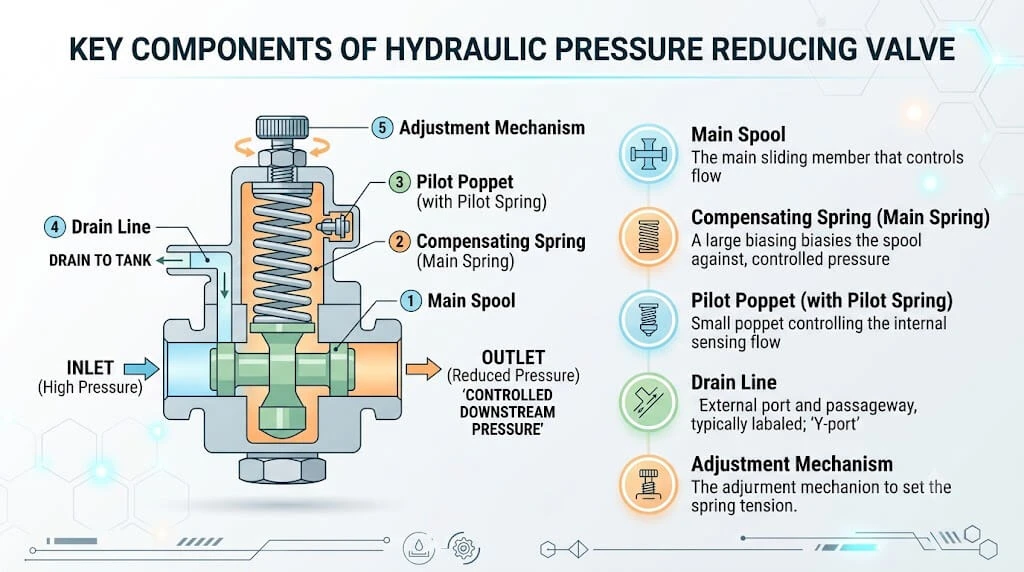
Main Spool

The throttling element. Its position determines the size of the flow restriction and thus the pressure drop. Spool lands must stay free of scoring and contamination.

Compensating Spring

Biases the spool open. In pilot designs, this spring is light because it only needs to overcome friction and keep the spool against its seat when the system is off.

Pilot Poppet

Found only on pilot-operated valves. Senses outlet pressure and controls the main spool spring chamber. A worn poppet seat causes pressure drift.

Drain Line

Carries leakage from the spring chamber to tank. Must connect directly to tank with no backpressure. Even 2-3 bar of backpressure on the drain line adds directly to the outlet pressure setting. This is the most common installation error.

Adjustment Mechanism

Usually a screw with locknut. Some valves accept a pressure gauge port at the spring chamber for monitoring. Proportional solenoid versions replace the mechanical adjuster with electrical control.

Where Engineers Use Hydraulic Pressure Reducing Valves
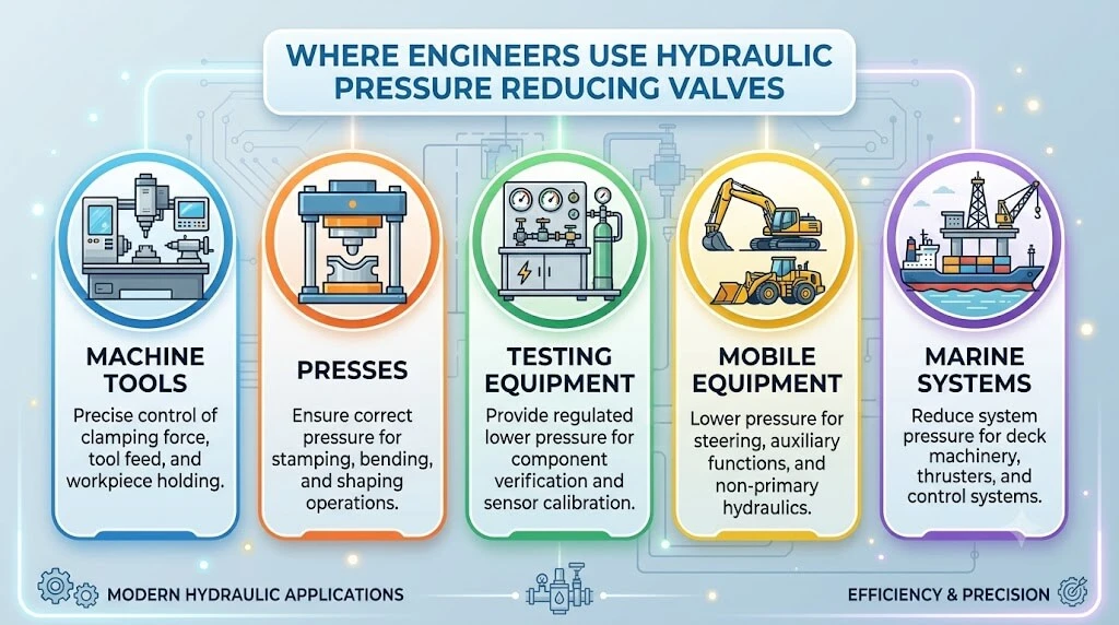
Where Engineers Use Hydraulic Pressure

Multi-pressure circuits appear everywhere in industrial hydraulics.

Machine Tools

Clamping cylinders hold workpieces at 210 bar. The feed drive operates at 100 bar or lower. A reducing valve on the feed circuit prevents the lower-pressure components from seeing full system pressure.

Presses

Main ram pressure might reach 350 bar during forming. Ejector circuits often run at 70-100 bar. A reducing valve protects ejector seals and reduces heating in the return lines.

Testing Equipment

Test stands sometimes supply multiple test points at different pressures from one pump bank. Each branch gets its own reducing valve. Isolation between test points prevents cross-interference.

Mobile Equipment

Auxiliary functions like brake circuits or pilot systems frequently need lower pressure than the main working circuits. Compact cartridge-style reducing valves fit inside manifold blocks for these applications.

Marine Systems

The steering gear may run at 100 bar while deck machinery operates at 150 bar. A reducing valve on the steering circuit ensures consistent rudder response regardless of main pump pressure variations.

Advantages and Limitations

Every component involves tradeoffs. Here is an honest assessment.

Advantages

  • Maintains stable downstream pressure despite inlet fluctuations
  • Protects lower-rated components from overpressure
  • Reduces heat generation in branch circuits compared to using orifices or fixed restrictors
  • Allows one pump to serve multiple pressure levels
  • Pilot-operated types offer precise regulation with minimal pressure override

Limitations

  • Generates heat across the pressure drop. Power loss equals flow times pressure drop divided by efficiency. A 50 L/min flow dropping from 210 bar to 105 bar wastes roughly 8.7 kW of heat.
  • Requires a dedicated drain line to the tank. Installers overlook this.
  • Response speed lags behind direct-acting relief valves. Sudden load changes cause brief pressure spikes.
  • Not suitable for primary system pressure control. Use a relief valve for that.
  • Contamination affects performance more than most other valve types. Small throttling gaps plug easily.

Common Problems and How to Fix Them

Field experience reveals repeatable failure patterns in any reducing valve deployment.

Problem 1: Outlet Pressure Creeps Up Over Time

Cause: Worn spool lands allow excess flow past the throttling edge. The valve cannot create enough restriction to maintain the set pressure.
Fix: Inspect the spool for scoring. If wear exceeds manufacturer limits, replace the valve or recondition the spool. Check fluid cleanliness. ISO 4406 code should be 18/16/13 or better for pilot-operated valves.

Problem 2: Pressure Oscillates or Hunts

Cause: Pilot instability, often from air entrainment in the pilot line, or too much pre-fill pressure variation at the inlet.
Fix: Bleed air from the pilot line. Add an accumulator near the valve inlet if pump ripple is severe. Verify the pilot orifice is not partially blocked.

Problem 3: Outlet Pressure Reads Higher Than Set

Cause: Backpressure on the drain line. Every bar of drain backpressure adds to outlet pressure.
Fix: Reroute the drain line directly to tank with no restrictions. Ensure the drain line is not teed into a loaded return line.

Problem 4: Valve Gets Hot

Cause: Normal heat generation from the pressure drop, or excessive flow through an undersized valve forcing a large pressure differential.
Verify: Calculate power loss. If losses exceed 3-4 kW continuously, consider upsizing the valve or redesigning the circuit to reduce the pressure drop requirement.

Selecting the Right Hydraulic Pressure Reducing Valve

Follow this process. Skip steps and the valve will not perform.

Step 1: Define Pressure Requirements

List your maximum inlet pressure, desired outlet pressure, and acceptable pressure variation. Inlet pressure should stay at least 10-15 bar above the outlet setting at all times. This margin ensures the valve can throttle properly even during minor inlet dips.

Step 2: Determine Maximum Flow

Calculate the peak flow rate the valve must pass. Size the valve so peak flow falls within 60-80% of its rated capacity. Running at 95% of rating causes excessive pressure drop and heat.

Step 3: Choose Direct-Acting or Pilot-Operated

Use this decision matrix:
Factor Choose Direct-Acting Choose Pilot-Operated
Flow rate
Under 30 L/min
Over 40 L/min
Precision required
Moderate (+/- 10%)
High (+/- 3-5%)
Cost priority
Budget-sensitive
Performance-sensitive
Available space
Limited
Standard subplate mount
System cleanliness
Fair
Good filtration mandatory

Step 4: Verify Drain Line Capacity

Ensure the drain line can carry maximum leakage flow without building backpressure. For pilot-operated valves at high flow, drain flow can reach 0.5-1.5 L/min. Size the drain line accordingly.

Worked Example

A machine tool needs a feed circuit at 105 bar. Main system pressure is 245 bar. Peak feed flow is 45 L/min. Filtration is good at ISO 18/16/13.
 
Given the 45 L/min flow and need for stable feed pressure, select a pilot-operated reducing valve rated for at least 60 L/min. Inlet-to-outlet ratio is 2.3:1, well within typical capability. Choose a CETOP 3 or NG6 size valve with 315 bar max inlet rating. Set outlet to 105 bar. Route the drain line directly to the tank with a minimum 6 mm diameter tube.

Installation and Adjustment Tips

Installation and Adjustment Tips
Years of fieldwork produced these practical rules.

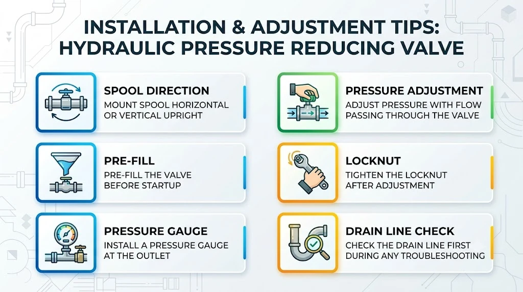
Mount the valve with the spool horizontal or vertical upright.

Side-mounted spools in some designs can experience uneven wear due to gravity effects on the spool. Check your manufacturer’s orientation guidance.

Pre-fill the valve before startup.

Dry start damages internal surfaces. Crack the inlet fitting slightly, run the pump briefly to push oil through, then tighten before bringing the system to pressure.

Adjust pressure with flow passing through the valve.

A hydraulic pressure reducing valve behaves differently at zero flow versus operating flow. Always set pressure under normal operating conditions.

Tighten the locknut after adjustment.

Vibration loosens adjustment screws. A drifting pressure setting causes production problems within days.

Install a pressure gauge at the outlet.

Permanent gauge ports let operators verify pressure without extra test equipment. Gauge readings also reveal developing problems early.

Check the drain line first during any troubleshooting.

Eight out of ten service calls trace back to restricted or misrouted drains. Save time by checking this first.

FAQ

What is the difference between a pressure reducing valve and a relief valve?

A relief valve is normally closed. It opens only when system pressure exceeds its setting. A hydraulic pressure reducing valve is normally open. It throttles flow to maintain lower outlet pressure. Relief valves protect the system. Reducing valves serve branch circuits.

Can a pressure reducing valve replace a relief valve?

No. They perform opposite functions. A reducing valve cannot limit maximum system pressure. Always install a relief valve as the primary safety device.

Why does my reducing valve get hot?

Heat comes from the energy lost across the pressure drop. Flow multiplied by pressure drop gives the power dissipated as heat. Reduce heat by minimizing the pressure drop or downsizing flow through the valve.

How close to inlet pressure can I set the outlet pressure?

Most valves require at least a 10-15 bar differential. Some pilot designs need 20-30 bar. Consult the manufacturer’s pressure-drop curve for your specific model.

What happens if the drain line plugs?

Outlet pressure rises by the amount of backpressure on the drain. A 5 bar drain blockage adds 5 bar to your outlet setting. The valve still functions but at the wrong pressure.

Conclusion

A hydraulic pressure reducing valve solves a specific problem: delivering stable lower pressure to part of a circuit while the rest runs higher. Proper selection means matching flow range, pressure band, and control precision to your application. Pilot-operated designs serve high-flow, precision needs. Direct-acting covers simple, low-cost requirements. Watch the drain line, keep the oil clean, and set pressure under real operating conditions. Get those basics right and these valves run reliably for years.

Related Articles

Scroll to Top
Shoot Us An Email

Professional Manufacturer