
Introduction
Heavy machinery needs to move big loads with precise control. Hydraulic drive systems do this by converting mechanical input into pressurized fluid, then back into motion at the load. You find them on excavators, hydraulic presses, winches, crushers, and marine thrusters.
This guide covers how a complete drive package works. It compares hydraulic power transmission with electric and mechanical alternatives. It breaks down where efficiency actually goes and gives you sizing math you can apply to a real machine.
What is a Hydraulic Drive System
A hydraulic drive system transmits power using pressurized fluid. A prime mover, usually an electric motor or diesel engine, turns a hydraulic pump. The pump pushes oil through lines to a hydraulic motor or cylinder. That motor converts the oil’s pressure and flow back into mechanical torque or linear force.
The core advantage is power density. A small hydraulic motor produces more torque than an electric motor of the same physical size. Fluid carries force at a higher energy density than copper and steel. That explains why hydraulic drive systems dominate heavy mobile equipment. A 200 kW excavator runs on compact hydraulic motors. An electric drive matching that output would need a much larger package.
How a Hydraulic Drive System Works
Power flows through four stages. The prime mover spins the pump. The pump converts shaft speed and torque into oil flow at pressure. Lines carry that oil to a hydraulic motor or cylinder. The motor then turns pressure and flow back into shaft torque and speed at the load.
The math is straightforward. Hydraulic power equals pressure times flow, divided by a constant. In SI units, power in kilowatts equals pressure in bar times flow in liters per minute, divided by 600. Double the pressure, and you double the power, as long as the flow holds steady.
A relief valve or pressure compensator limits the maximum pressure. A flow control or variable displacement pump governs the speed. Reversing the flow direction reverses a motor or retracts a cylinder. The fluid returns to a reservoir, sheds heat, gets filtered, and cycles back to the pump inlet.
Main Components of Hydraulic Drive Systems
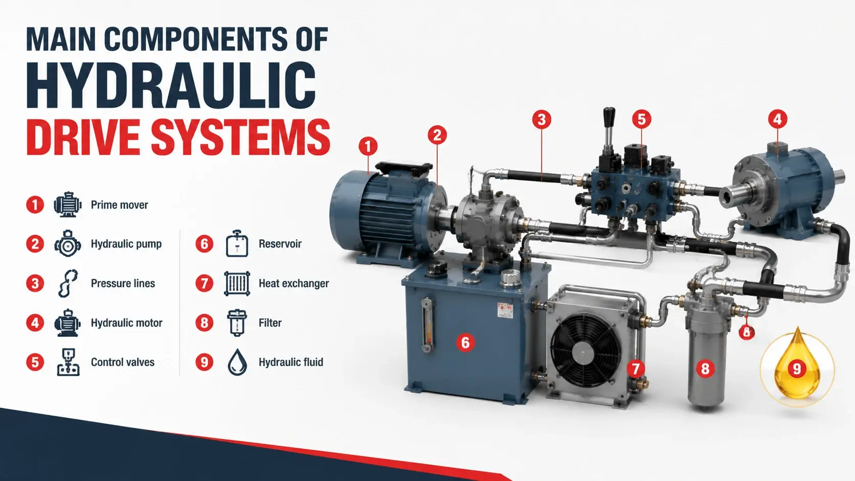
| Component | Function | Typical Specification |
|---|---|---|
Prime mover |
Supplies mechanical input |
Electric motor (IE2-IE4) or diesel engine, 5-500 kW |
Hydraulic pump |
Converts input to flow and pressure |
Gear, vane, or axial piston; 10-450 cc/rev; up to 700 bar |
Pressure lines |
Carry oil to the actuator |
SAE 100R1/R2 hose or steel tube; ISO 6149 or SAE J1926 ports |
Hydraulic motor |
Converts flow and pressure to torque |
Gear, vane, or axial piston; 5-350 bar continuous |
Control valves |
Direct flow, limit pressure, regulate speed |
Directional, relief, flow control, proportional |
Reservoir |
Stores fluid, sheds heat, releases air |
1-3 times pump flow per minute in open loop systems |
Heat exchanger |
Rejects waste heat |
Air or water cooled; sized to 15-30% of input power |
Filter |
Removes contamination |
ISO 4406 20/18/15 return line; 10 micron pressure line |
Hydraulic fluid |
Transmits power, lubricates, cools |
ISO VG 32-68; viscosity index above 90 |
Open Loop vs Closed Loop Hydraulic Drive Systems
Two architectures cover most applications. Open-loop drives send spent oil back to a reservoir each cycle. The pump draws fresh oil from that tank. Closed-loop drives circulate oil directly between the pump and motor, with a small charge pump making up for leakage.
Open loop suits machines that run several actuators from one pump bank. The reservoir gives you easy filtration, simple heat rejection, and room for multiple valves. Most industrial presses and material handlers use open-loop drives.
Closed loop fits single rotary drives that need precise bidirectional speed control at high pressure. Travel drives, winches, and marine thrusters run closed loop at 350-450 bar. The reservoir stays small because only makeup and flush oil leaves the loop.
| Factor | Open Loop Drive | Closed Loop Drive |
|---|---|---|
Return path |
Oil returns to tank each cycle |
Oil circulates pump to motor |
Direction control |
Directional valve |
Pump swashplate reversal |
Reservoir size |
Large, full flow |
Small, charge volume only |
Typical pressure |
Up to 350 bar |
350-450 bar |
Best fit |
Multi-actuator machines |
Single bidirectional rotary drive |
Hydraulic vs Electric vs Mechanical Drives
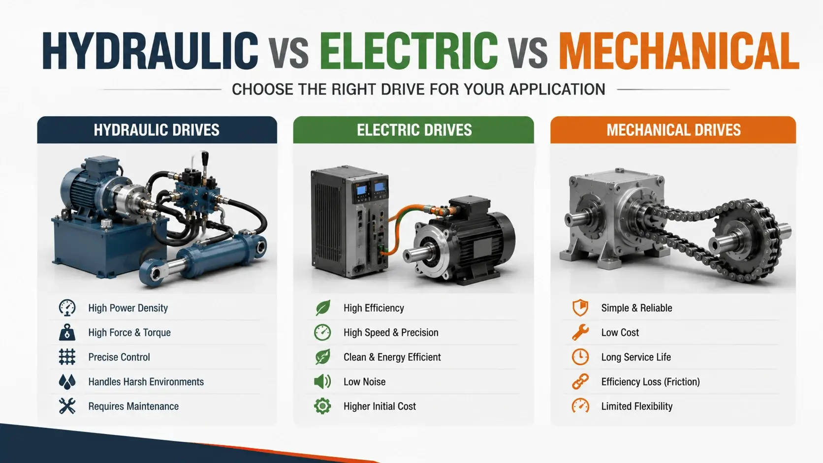
Engineers choose a drive technology by comparing power density, controllability, cost, and the working environment. Each option has a sweet spot.
Mechanical drives, like gearboxes and belt drives, transfer power through solid shafts and teeth. They are efficient and simple. But they lock the load to the prime mover positionally, and stalling a mechanical drive breaks parts. You cannot easily route power around corners without a complex shaft arrangement.
Electric drives use motors and cables. They are clean, quiet, and easy to instrument. The limitation is size and weight at high torque. An electric motor that matches a hydraulic motor’s stall torque weighs several times more and occupies more space. Electric drives also struggle in wet, dirty, or explosive environments unless you spend heavily on enclosures.
Hydraulic drive systems win where you need high torque in a small package. They offer flexible power routing through hoses and tolerate stalling without damage. A hydraulic motor holds full torque at zero speed indefinitely. That is something electric motors only do with active current control and a cooling penalty.
| Factor | Hydraulic | Electric | Mechanical |
|---|---|---|---|
Power density |
High |
Medium |
High |
Torque density |
Very high |
Medium |
High |
Stall tolerance |
Full torque, indefinite |
Limited, needs cooling |
Poor, breaks parts |
Power routing |
Flexible via hoses |
Flexible via cables |
Fixed shaft geometry |
Efficiency |
60-85% system |
85-95% system |
90-98% per stage |
Controllability |
Good with proportional valves |
Excellent with VFD |
Fixed ratio |
Environment tolerance |
Good with sealing |
Needs enclosure |
Good with shielding |
Types of Hydraulic Drive Systems
Hydraulic drive systems split into three families based on how they manage flow and combine with other technologies.
Hydrostatic drives pair a variable displacement pump with a hydraulic motor. The pump controls motor speed and direction by changing its swashplate angle. This is the backbone of mobile equipment travel drives. Most run closed loop at 350-450 bar.
Electro-hydraulic drives add electronic control on top of the hydraulic power path. Proportional and servo valves, fed by amplifiers and controllers, regulate pressure and flow precisely. These drives show up in injection molding machines, test stands, and simulation platforms. They suit applications where you need closed-loop position or force control.
Hybrid hydraulic drives combine a hydraulic accumulator with a pump-motor and an electric or engine input. The accumulator stores energy during braking or low-load periods and releases it for peak demand. City buses and refuse trucks use this layout to cut fuel consumption by 20-30% on stop-and-go routes.
Efficiency and Power Losses
System efficiency in hydraulic drive systems usually lies between 60 and 85 percent. That number surprises people who expect hydraulics to match the 90-plus percent of a good gearbox. The losses come from three places.
Volumetric losses are internal leakage. Piston shoes, valve plates, and spool clearances all leak a few percent of flow past their gaps. A worn pump leaks more. Case drain flow tells you how much. Anything above 5-10% of rated flow signals a pump heading for rebuild.
Mechanical losses come from friction. Bearings, seals, and the fluid’s own viscous drag all eat input torque. These losses stay fairly constant and run 3-8% across a healthy pump and motor.
Thermal losses are the energy that becomes heat. Every pressure drop across a valve turns into heat. So does every restriction in a line and every gallon of bypassed flow. The exchanger must reject all of it. A poorly routed system with small lines and too many valves can waste 15% of input power as heat.
The practical takeaway: efficiency depends heavily on architecture and component sizing, not on the pump’s datasheet number alone. Two systems with the same pump can differ by 15 percentage points based on architecture and valve count.
Sizing a Hydraulic Drive System
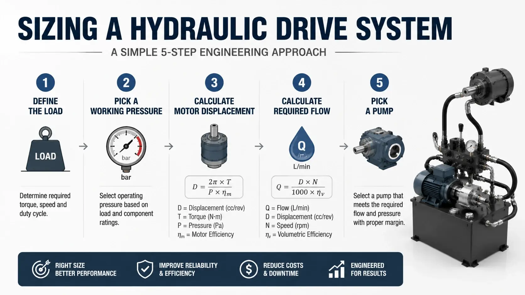
Sizing starts at the load and works backward. You need the load’s torque and speed, then you pick pressures and flows that deliver them.
Step one: define the load
Get the required torque in newton-meters and the speed in revolutions per minute. For a rotary drive, torque equals the load force times the radius. For a winch drum lifting 50 kN at 0.5 meter radius, the torque is 25,000 Nm.
Step two: pick a working pressure
Mobile drives run 280-420 bar. Industrial presses run 210-300 bar. Higher pressure means smaller displacement and lighter components, but tighter leakage control and costlier hardware.
Step three: calculate motor displacement
Motor displacement in cc per rev equals torque in Nm times 20 times pi, divided by pressure in bar. For 25,000 Nm at 350 bar, displacement works out to about 4,500 cc/rev. You would use a low-speed, high-torque motor or a reduction gear with a smaller motor.
Step four: calculate required flow
Flow in liters per minute equals motor displacement in cc/rev times speed in rpm, divided by 1,000. At 60 rpm, the 4,500 cc/rev motor needs 270 L/min.
Step five: pick a pump
The pump must supply that flow at that pressure, plus a margin for leakage and control overhead. Add 5-15% to the calculated flow. Then match the prime mover power. Input kW equals pressure in bar times flow in L/min, divided by 600, divided by pump efficiency.
Advantages
These systems earn their place through a few concrete traits.
High power density lets you put serious torque in a tight envelope. A hydraulic motor the size of a coffee can produces 500 Nm. An equivalent electric motor needs a much bigger frame.
Stall tolerance is the second advantage. A hydraulic motor holds full torque at zero speed without overheating. The relief valve and cooling must hold up. Electric and mechanical drives cannot do this as cleanly.
Flexible power routing matters on mobile equipment. Hoses bend around frames and articulate with booms. A rigid shaft drivetrain cannot follow a folding excavator arm.
Built-in overload protection comes standard. A relief valve caps pressure and protects the whole circuit. Mechanical drives shear keys or break teeth instead.
Limitations
Hydraulic drive systems have real drawbacks that engineers must weigh.
Heat is the biggest one. Every inefficiency becomes heat that the exchanger must reject. Undersized cooling is the most common cause of premature failure in hydraulic drives.
Contamination sensitivity ranks second. Particles above 10 microns wear pumps and motors fast. A system without proper filtration and breathers will destroy its own components within hundreds of hours.
Noise can be a problem on electric-motor-driven units, though diesel-driven mobile systems mask it. Pump pulsation and valve shifting both contribute.
Fluid maintenance is ongoing. You check viscosity, water content, and particle counts regularly. Ignoring the fluid is the fastest route to a shortened service life.
Industrial Applications
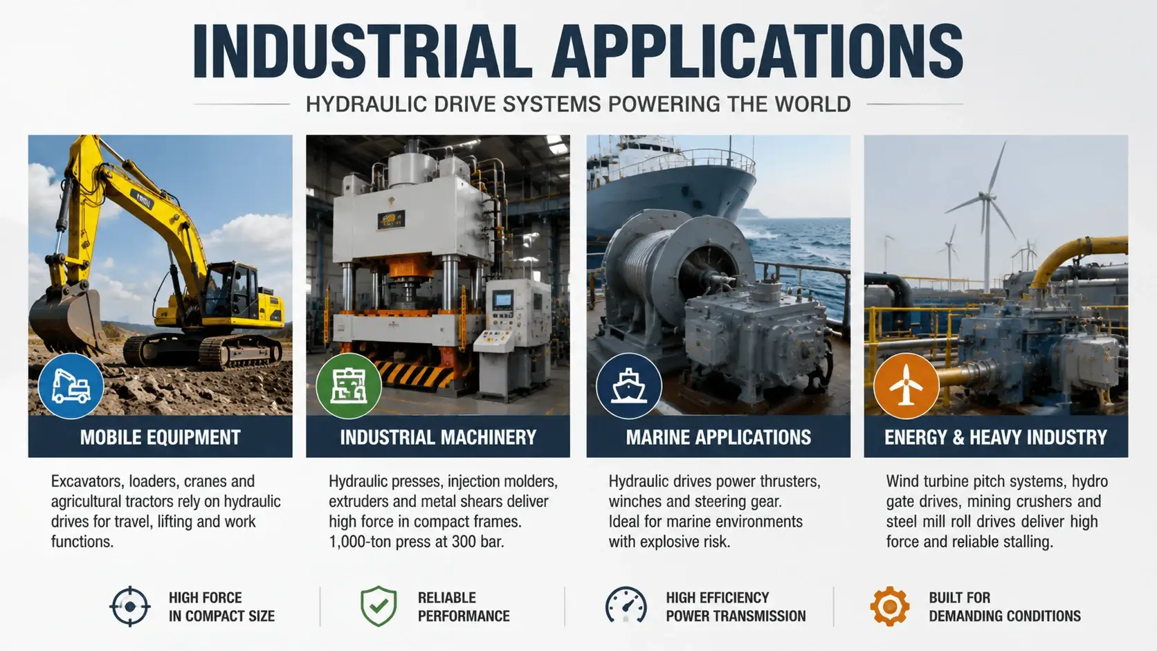
Mobile equipment is the largest market. Excavators, loaders, cranes, and agricultural tractors all run on hydraulic drive systems. Travel drives use closed-loop hydrostatic transmissions. Boom and bucket functions run open loop with multiple valves.
Industrial machinery comes next. Hydraulic presses, injection molders, extruders, and metal shears rely on hydraulic drives for high force in compact frames. A 1,000-ton press runs at 300 bar on cylinders that fit inside the machine bed.
Marine applications use hydraulic drives for thrusters, winches, and steering gear. Shipboard environments favor hydraulics because electric drives need heavy explosion-proof enclosures near fuel and cargo.
Energy and heavy industry round out the list. Wind turbine pitch systems, hydroelectric gate drives, mining crushers, and steel mill roll drives all depend on hydraulic power transmission. They deliver high force and reliable stalling under load.
Common Problems and Troubleshooting
Most failures in hydraulic drive systems trace back to a handful of root causes.
Low charge pressure in a closed loop kills the pump fast. If the charge pressure drops below 15 bar, the loop cavitates, and the piston shoes hammer the swashplate. Check the charge pump, the charge relief valve, and the suction filter first.
Overheating points to a blocked heat exchanger, low oil level, or excess flow bleeding across relief valves. Measure tank temperature. Anything above 70 degrees Celsius degrades the oil and the seals.
Sluggish response usually means contamination in a valve, a worn pump losing displacement, or air in the lines. Check particle counts, case drain flow, and bleed the high points.
Cavitation sounds like gravel in the pump. It comes from a clogged suction filter, high oil viscosity on cold starts, or a suction line too small. Fix the inlet conditions before the pump destroys itself.
Noise and vibration often trace to air entrainment, misaligned couplings, or resonant line lengths. Address the air first, then check mounting and add pulsation dampeners if the lines sing.
Maintenance Tips
Fluid health comes first. Sample the oil every 500 hours for particle count, viscosity, and water content. Keep the fluid within ISO 4406 20/18/15 for general systems and 18/16/13 for high-pressure piston pumps.
Filtration needs attention. Change return filters on schedule, and watch the pressure drop indicators. A filter that silently stops filtering.
Charge pressure in closed-loop drives needs a weekly check. A slow drop signals charge pump wear or a leaking check valve. Catch it before the main pump suffers.
Case drain flow is the cheapest wear indicator you have. Measure it with a bucket and a stopwatch at scheduled intervals. Trend the number. A steady rise means internal wear is accelerating.
Heat exchangers need cleaning. On air-cooled units, fin fouling cuts capacity fast. Clean them when you service the radiator. On water-cooled units, check for scale and flow restrictions.
FAQ
What is a hydraulic drive system?
A hydraulic drive system transmits power using pressurized fluid. A prime mover drives a pump, which sends oil to a hydraulic motor or cylinder. The motor converts that oil’s pressure and flow back into mechanical torque or force.
How does a hydraulic drive system work?
The prime mover spins a hydraulic pump. The pump pushes oil at pressure through lines to a motor. The motor turns that pressure and flow into shaft torque. Control valves regulate pressure, flow, and direction. The fluid returns to a reservoir, cools, filters, and repeats the cycle.
Hydraulic or electric drive, which is better?
It depends on the load. Hydraulic drives win on torque density, stall tolerance, and flexible power routing through hoses. Electric drives win on efficiency, cleanliness, and precise speed control. Heavy mobile equipment leans hydraulic. Factory automation leans electric. Many modern machines combine both.
How efficient is a hydraulic drive system?
Realistic system efficiency runs 60-85 percent. Volumetric leakage, mechanical friction, and pressure drops across valves all contribute. Two systems with the same pump can differ by 15 percentage points based on architecture and valve count.
How do you size a hydraulic drive system?
Start with the load torque and speed. Pick a working pressure. Calculate motor displacement from torque and pressure. Calculate required flow from displacement and speed. Size the pump with a 5-15% flow margin, then match prime mover power to pressure and flow.
What are common hydraulic drive failures?
Low charge pressure, overheating, contamination, and cavitation cause most failures. Charge loss destroys closed loop pumps in hours. Heat above 70 degrees Celsius degrades oil and seals. Particles above 10 microns wear pumps fast. Cavitation from poor inlet conditions damages pumps quickly.
Conclusion
Hydraulic drive systems trade a bit of efficiency for unmatched torque density, stall tolerance, and flexible power routing. They earn their place on heavy mobile equipment, high-force presses, and marine drives. Electric and mechanical alternatives cannot match the package. Choose your architecture, size your components from the load backward, and keep the fluid clean and cool. Do that, and a well-built hydraulic drive will run for thousands of hours.