Hydraulic Ball Valve: Selection and Application Guide for Hydraulic Systems

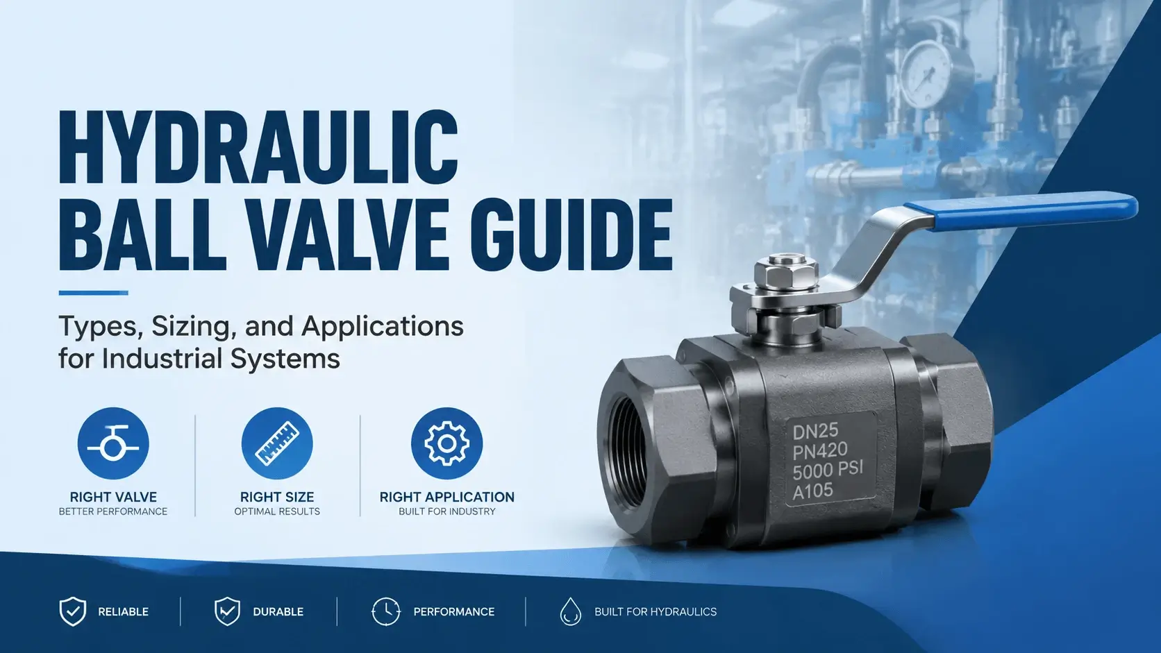
Hydraulic Ball Valve Guide- Types, Sizing, and Applications for Industrial Systems

Table of Contents

A hydraulic ball valve sits in a line for one reason: to shut off flow completely or let it pass with minimal restriction. You find them on hydraulic power unit outlets, manifold blocks, test stand panels, and cylinder service ports. 
 
Unlike needle valves or throttle valves meant for metering, a ball valve is an isolation device. It has two positions: open or closed. That simplicity makes it reliable, but only if you pick the right design for the pressure, fluid, and duty cycle involved.
 
This guide covers what distinguishes a hydraulic ball valve from general-purpose versions, how floating and trunnion designs behave at different pressures, which seat materials survive in hydraulic oil, and how to avoid the failure modes that cause leaks and stuck valves in the field.

What is a Hydraulic Ball Valve
What is a Hydraulic Ball Valve
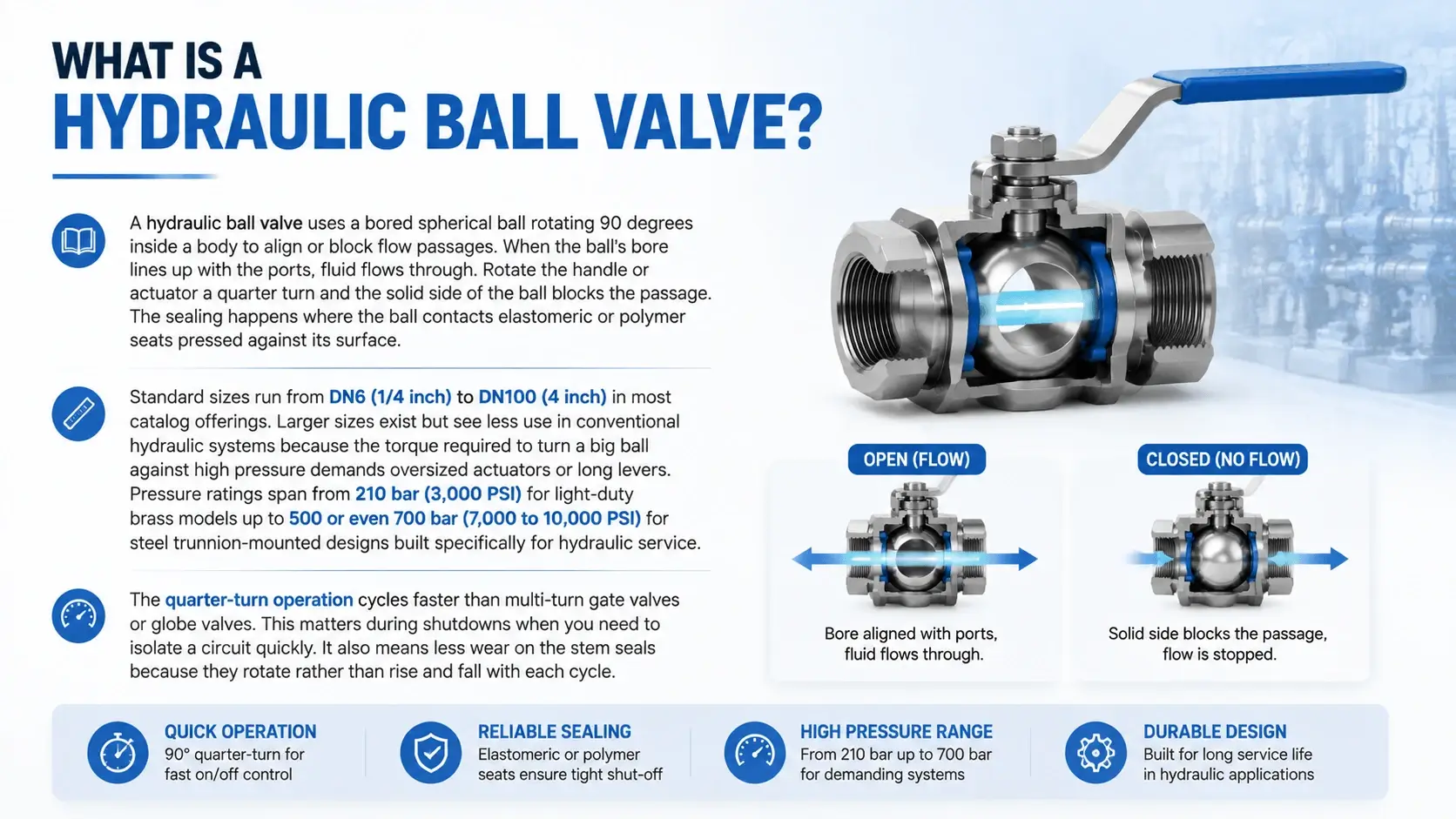
A hydraulic ball valve uses a bored spherical ball rotating 90 degrees inside a body to align or block flow passages. When the ball’s bore lines up with the ports, fluid flows through. Rotate the handle or actuator a quarter turn and the solid side of the ball blocks the passage. The sealing happens where the ball contacts the elastomeric or polymer seats pressed against its surface.
 
Standard sizes run from DN6 (1/4 inch) to DN100 (4 inch) in most catalog offerings. Larger sizes exist but see less use in conventional hydraulic systems because the torque required to turn a big ball against high pressure demands oversized actuators or long levers. Pressure ratings span from 210 bar (3,000 PSI) for light-duty brass models up to 500 or even 700 bar (7,000 to 10,000 PSI) for steel trunnion-mounted designs built specifically for hydraulic service.
 
The quarter-turn operation cycles faster than multi-turn gate valves or globe valves. This matters during shutdowns when you need to isolate a circuit quickly. It also means less wear on the stem seals because they rotate rather than rise and fall with each cycle.

Floating vs. Trunnion Mounted Designs

The way the ball sits inside the body determines how much pressure a ball valve of this type can handle. Two designs dominate: floating ball and trunnion-mounted.

Floating ball

The ball hangs from the stem with no bottom support. System pressure pushes the ball against the downstream seat. The higher the pressure, the harder the seat compresses. This works fine up to about 200 bar (3,000 PSI).
 
Above that, the seating force gets so high that operating torque spikes and the seat wears faster. Floating ball valves cost less and suit low-pressure hydraulic systems like lubrication circuits, auxiliary lines, and pilot control manifolds.

Trunnion mounted

The ball has a lower shaft or bearing in addition to the top stem. The trunnion absorbs the hydraulic thrust so the ball cannot shift downstream. Seats are spring-loaded against the ball rather than pressure-loaded. Operating torque stays relatively constant across the pressure range.
 
Trunnion valves handle 250 to 700 bar, depending on body material and seat construction. You see them on main pump isolations, high-pressure test stands, and heavy equipment hydraulic systems.
Design Max Pressure Torque Behavior Typical Cost Range Best Use
Floating
200 bar
Rises sharply with pressure
Low to moderate
Auxiliary circuits, low-pressure HPUs
Trunnion
500-700 bar
Stable across pressure range
Moderate to high
Main system isolation, test stands
If your system runs below 150 bar and cycles infrequently, a floating design will do the job without the extra cost of trunnion bearings. Once you cross 200 bar on a regular basis, step up to trunnion mount. The torque reduction alone justifies the price difference when operators actuate the valve daily.

Bore Options: Full Bore vs. Reduced Bore

The diameter of the hole through the ball affects flow capacity and cleaning access.

Full bore (full port)

The ball bore matches the nominal port size. A DN25 full-bore valve has a 25 mm hole through the ball. Flow coefficient stays high and pressure drop stays low. You can also run a pigging brush or inspection camera through a full-bore valve, which helps during system flushing. Full bore costs more because the ball body must be larger to maintain wall thickness around the bigger hole.

Reduced bore (reduced port)

The ball bore is one or two pipe sizes smaller than the port. A DN25 reduced-bore valve might have a 15 or 20 mm bore. The velocity increases through the restriction, which raises pressure drop slightly.
 
For most hydraulic applications running 2 to 5 m/s line velocity, the drop amounts to 0.5 to 2 bar depending on flow rate. Reduced bore valves are smaller, lighter, and cheaper. They work fine where the extra pressure drop does not affect system performance.
 
Choose full bore when you need maximum flow, minimal pressure drop, or the ability to clean the line through the valve. Choose reduced bore for cost-sensitive applications where space is tight and flow rates stay moderate.

Port Configurations: 2-Way and 3-Way Designs
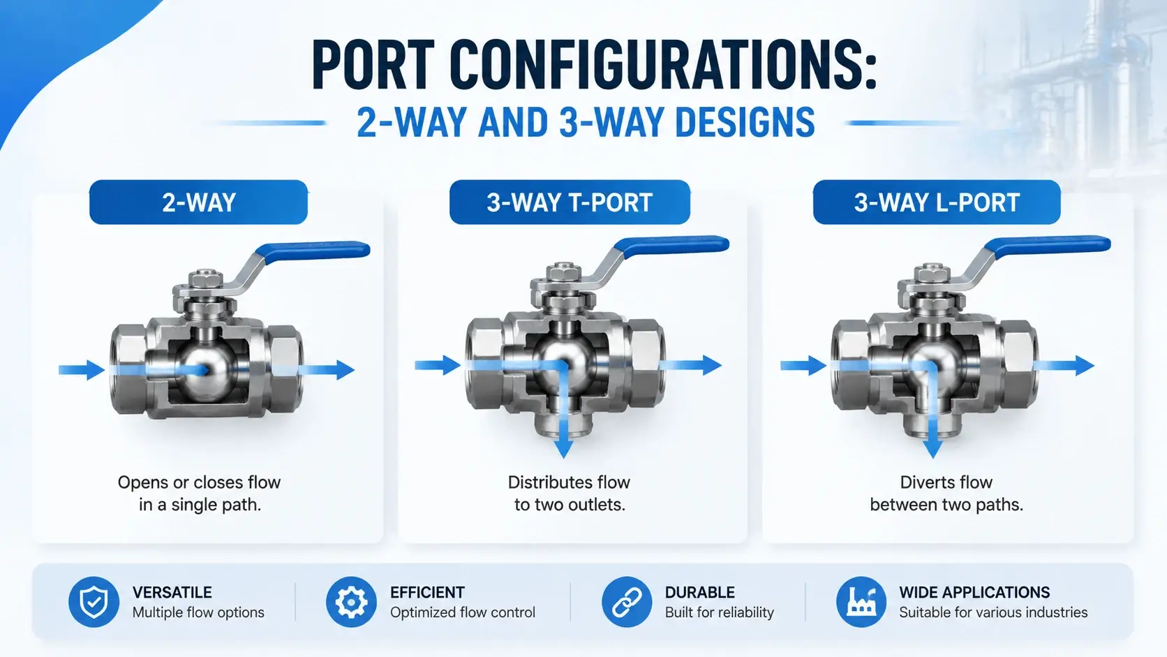
Most ball valve installations in hydraulic systems use a simple 2-way (2/2) configuration: one inlet, one outlet, open or shut. But 3-way designs have a place in certain hydraulic circuits.

2-way

Straight isolation. Used everywhere: pump discharge, tank return lines, cylinder service ports, filter housings. Available in full or reduced bore, floating or trunnion.

3-way T-port

The ball has an L-shaped or T-shaped passage. In T-port design, all three ports can connect simultaneously in one position. This lets you divert flow from one outlet to another while maintaining a common inlet, or combine two inlet streams into one outlet. T-port valves show up in sampling systems, bypass arrangements, and some load-sensing circuits where you switch between multiple pressure sources.

3-way L-port

The L-shaped passage connects two ports at a time while blocking the third. Each handle position selects a different pair. L-port suits directional switching applications where you alternate between two circuits, such as selecting between two cylinders or two work modes.
 
For standard hydraulic isolation, stick with 2-way. Add 3-way only when the circuit logic requires flow diversion or source selection that would otherwise need two 2-way valves and more fittings.

Key Components of a Hydraulic Ball Valve
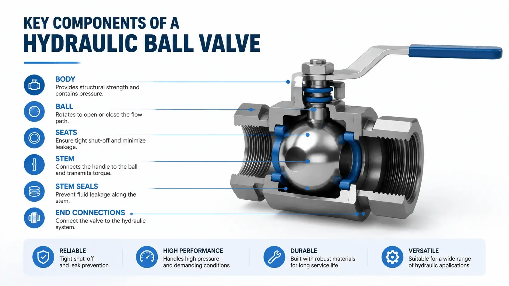
Understanding the parts helps you diagnose problems and specify replacements correctly.

Body

The main housing. Carbon steel (A105 or WCB) covers most hydraulic applications up to 420 bar. Stainless steel 316 handles corrosive fluids or washdown environments. Forged bodies rate higher than castings for pressure and fatigue strength. Avoid cast iron bodies in any hydraulic service above 100 bar.

Ball

Usually 316 stainless steel or chrome-plated carbon steel. Some high-spec valves use Stellite or tungsten carbide coating for abrasive service. The ball surface finish directly affects seat life and shutoff quality. A rough ball scours the seat every time the valve operates.

Seats

Soft seats made from PTFE, PEEK, nylon, or glass-filled composites provide the seal against the ball. Metal seats exist for high-temperature service but rarely appear in hydraulic applications because hydraulic oil stays below 80 degrees C in properly designed systems.

Stem

Connects the ball to the handle or actuator. Must resist the torque applied during operation and the side load from system pressure trying to push the ball off its seat. Blowout-proof stems prevent the stem from ejecting outward if the body internal pressure exceeds safe limits.

Stem seals

O-rings or packing glands around the stem keep fluid inside the valve. Material selection here is critical for hydraulic service. Standard nitrile (NBR) works for mineral oils up to 100 degrees C. Viton (FKM) handles higher temperatures and some synthetic fluids. EPDM suits phosphate ester (HFD-R) fluids but swells badly in mineral oil.

End connections

Threaded (NPT, BSPP, metric), flanged (ANSI, DIN, JIS), or hydraulic-specific (SAE J1926, ISO 6149, ISO 16028 flat-face). Match the valve ports to your fitting system or expect leaks.

Seat Materials for Hydraulic Service

The seats determine shutoff quality, temperature range, and chemical compatibility. Pick the wrong seat material and your valve leaks within weeks.
Material Max Temp (C) Pressure Limit Hydraulic Oil Compatibility Wear Resistance Cost
PTFE (unfilled)
200
210 bar
Excellent
Fair
Low
Glass-filled PTFE
230
350 bar
Excellent
Good
Moderate
PEEK
260
400 bar
Excellent
Very good
High
Nylon 6/6
100
210 bar
Good
Good
Low
PTFE/Carbon composite
260
420 bar
Excellent
Very good
High
PTFE is the default choice for most hydraulic applications of this kind. It seals well at low pressures, resists virtually all hydraulic fluids, and costs less than engineered polymers. Unfilled PTFE deforms under sustained high pressure (above 300 bar), which causes the seat to cold-flow into the clearance gap around the ball. Glass-filled PTFE reduces this problem by adding structural rigidity.
 
PEEK handles the highest combined pressure and temperature loads. Use it when the valve sees sustained operation above 200 bar and temperatures above 80 degrees C. The material resists cold flow better than PTFE and tolerates occasional dry operation during commissioning.
 
Nylon works for light-duty valves below 100 bar where cost matters more than maximum performance. It absorbs a small amount of moisture over time, which can cause slight dimensional change. Not recommended for critical shutoff applications.
 
Avoid using rubber or Buna-N seats in any valve rated above 150 bar. Rubber extrudes under high pressure and the resulting seat deformation creates a permanent leak path.
 

Pressure Ratings and Standards

Pressure ratings for these valves depend on body material, design class, and temperature. Do not assume a “600 class” valve from a plumbing catalog will handle 600 PSI in hydraulic service. Class ratings follow different scales depending on the standard.

ANSI class system

Class 150, 300, 600, 1500, and 2500 define pressure-temperature limits based on material and construction. For carbon steel WCB bodies at 38 degrees C (100 F): Class 150 equals about 20 bar, Class 300 reaches 50 bar, Class 600 hits 100 bar, Class 1500 goes to 250 bar, and Class 2500 reaches 420 bar. These numbers drop as temperature rises.

DN sizing

European catalogs use nominal diameter (DN) instead of inch sizes. DN10 equals roughly 3/8 inch, DN15 equals 1/2 inch, DN25 equals 1 inch, and so on. Always check the actual port thread or flange dimension because DN sizes vary slightly between standards.

Hydraulic-specific ratings

Reputable hydraulic valve manufacturers publish pressure ratings at actual hydraulic operating conditions, not just ambient-temperature water ratings. Look for ratings specified at 50 degrees C or 70 degrees C with ISO VG 46 or ISO VG 68 fluid. A valve rated 420 bar at room temperature might derate to 320 bar at 70 degrees C due to reduced seat strength and body allowable stress.
 
When in doubt, ask the supplier for the pressure rating at your specific operating temperature. If they cannot provide it, derate the published rating by 20 percent as a safety margin.

Sizing a Hydraulic Ball Valve

Sizing a Hydraulic Ball Valve
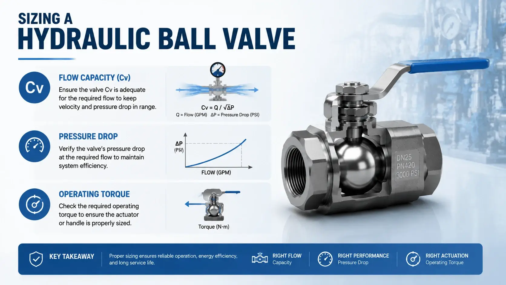
Sizing involves three factors: flow capacity, pressure drop, and operating torque.

Flow capacity (Cv)

The Cv coefficient tells you how many US gallons per minute of water pass through the valve with 1 PSI pressure drop. For hydraulic oil, adjust the Cv calculation for fluid specific gravity (typically 0.85 to 0.90 for mineral oil). A rule of thumb: size the valve so that velocity through a reduced-bore unit stays below 6 m/s at maximum flow. Higher velocity erodes seats over time and causes cavitation noise near the throttled position.

Pressure drop

Calculate expected pressure drop at your maximum flow rate using the manufacturer’s Cv chart or flow coefficient table. If the drop exceeds 3 to 5 percent of your system pressure, consider moving up one size or switching to full bore. Excessive pressure drop across an isolation valve wastes energy and generates heat in the fluid.

Operating torque

Check the breakaway torque spec at your system pressure, not just at zero pressure. A DN25 floating ball valve might require 5 Nm at zero pressure but 25 Nm at 200 bar. Make sure your handle lever length, gear operator, or actuator can deliver that torque with a safety factor of 1.5 to 2.0. Underpowered actuators stall mid-stroke, leaving the ball partially open in a position where the seat wears unevenly.

Common Failure Modes

Common Failure Modes
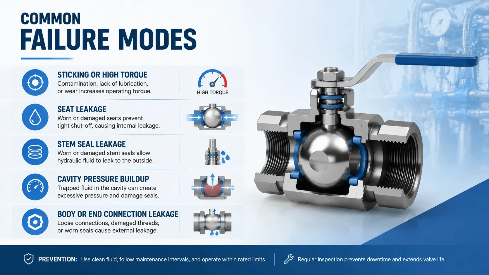
Field experience shows the same problems repeating across ball valve installations in hydraulic systems.

Sticking or high torque

Contamination particles lodge between the ball and seat. Rust forms on carbon steel balls during shutdown periods. Polymer seats cold-flow under sustained pressure and grip the ball surface. Prevention: install a strainer upstream, use stainless steel or coated balls in systems that sit idle for weeks, and exercise the valve monthly even if isolation is not currently needed.

Seat leakage

The valve drips from the downstream port when closed. Causes include scratched ball surfaces, debris embedded in the seat, seat extrusion (material forced into the clearance gap), or thermal expansion mismatch between the ball and seat. If the seat is damaged, replace it. Ball scratches deeper than 0.05 mm usually require ball replacement or regrinding, which most users treat as a valve-level repair.

Stem seal leakage

Fluid weeps from around the handle stem. The O-ring hardened from heat or age, the stem scored from side loading, or the seal material swelled incompatibly with the hydraulic fluid. Replace the stem seal kit. While you have it apart, check the stem surface for scoring marks. A grooved stem will ruin new seals within weeks.

Cavity pressure buildup

In double isolation setups (two valves in series), fluid trapped between them expands when heated or contracts when cooled. If no relief path exists, cavity pressure can exceed the body rating even though both upstream and downstream pressures are low. Solution: install a bleed valve between the isolations, or use a valve with a built-in cavity relief port to tank.

Body or end connection leakage

Threaded joints back out from vibration. Flange gaskets degrade from heat cycling. Flat-face connections (ISO 16028) leak if the mating surface is scratched or the o-ring is pinched during assembly. Retorque threaded connections after initial pressurization. Replace flange gaskets whenever the valve is removed and reinstalled.

Maintenance and Troubleshooting

A ball valve of this type needs far less attention than a directional control valve or a pump, but it is not maintenance-free.

Inspection interval

Check externally for stem leaks and end connection weeps every three months in continuous operation. For intermittent-use equipment (standby pumps, emergency shutdown valves), cycle the valve manually once per month to prevent sticking and verify smooth operation.

Repair procedure

Most designs allow seat and stem seal replacement without removing the valve body from the line. Depressurize both sides of the valve first. Remove the body bolts or end caps. Extract the old seats and stem seals. Clean all parts with solvent and inspect the ball surface before installing new components. Reassemble with correct bolt torque sequence (usually star pattern, working from center outward).

Replacement criteria

Replace the entire valve if the body shows corrosion pitting deeper than 1 mm, the ball has deep scratches or flat spots, the trunnion bearings have visible play, or the body casting has cracks near the port threads. Repairing a valve in this condition costs more than a new one and risks in-service failure.

Selection Checklist

Use this list when specifying a ball valve for a new hydraulic application:

  1. Confirm maximum working pressure, including pressure spikes. Add a 25 percent safety margin above normal operating pressure.
  2. Determine the maximum flow rate and calculate the required Cv.
  3. Decide between a floating (below 200 bar) or a trunnion (above 200 bar) design.
  4. Choose full bore or reduced bore based on flow needs and budget.
  5. Select a 2-way or 3-way configuration based on circuit function.
  6. Verify seat material compatibility with hydraulic fluid type and maximum temperature.
  7. Match port connections to existing fitting system (SAE, ISO, NPT, BSP).
  8. Check operating torque at system pressure against the available actuation method.
  9. Confirm body material suits the environment (carbon steel for general use, 316 SS for corrosion).
  10. Verify cavity pressure relief if using a double isolation arrangement.

FAQ

Can I use a hydraulic ball valve for flow control?

You can, but you should not. Partially closing a ball valve creates high localized velocity through the narrow opening. This erodes the seat, damages the ball surface, and produces cavitation vibration that loosens pipe supports. Use a needle valve, throttle valve, or proportional directional valve for flow control. Reserve the ball valve for fully open or fully closed positions only.

Why does my ball valve leak after sitting closed for months?

Two common causes. First, debris trapped between the ball and the seat when the valve was last closed prevented full seating. When pressure was applied, the seat deformed around the particle and never recovered. Second, polymer seats cold-flow under sustained compression. The seat material slowly creeps into gaps around the ball, creating an uneven surface that no longer seals cleanly. Cycle the valve periodically (monthly minimum) to redistribute seat stress and dislodge contamination before it embeds.

What is the maximum pressure for a hydraulic ball valve?

It depends entirely on design and size. Small floating ball valves (DN6 to DN25) typically max out at 200 to 350 bar. Trunnion-mounted valves in carbon steel reach 420 to 500 bar. Special high-pressure designs with reinforced bodies and metal-to-metal secondary seals go to 700 bar. Always check the manufacturer’s datasheet for your specific size and material combination. Never assume pressure rating from valve appearance alone.

How do I choose between PTFE and PEEK seats?

Use PTFE for standard hydraulic service below 200 bar where the temperature stays under 80 degrees C. It costs less and seals reliably in mineral oil, HFA, HFB, and most HFD fluids. Step up to PEEK when pressure exceeds 200 bar, temperature exceeds 80 degrees C, or the valve cycles frequently under load. PEEK resists cold flow and wears better than PTFE, which extends seat life in demanding applications. The price difference is usually justified by longer replacement intervals.

Should I use a 2-way or 3-way ball valve for bypass arrangements?

For a simple bypass where you want to route flow around a component (filter, cooler, or standby pump), two 2-way valves arranged in a T-junction give you more flexibility than one 3-way valve. With separate 2-way valves, you can isolate either side independently and lock out a single leg for maintenance. A 3-way valve is compact and reduces fitting count, but it forces both paths to share a common sealing element. If that element fails, both circuits lose isolation. Use a 3-way when space is extremely limited, and the consequence of a single-point failure is acceptable.

Conclusion

A hydraulic ball valve seems like a simple component until you account for pressure effects on seat loading, fluid compatibility with stem seals, and cavity pressure risks in double-isolation setups.

Check pressure ratings at your actual operating temperature. Size for realistic torque at working pressure, not just at zero. And cycle the valve regularly even when it stays closed for long periods. These steps prevent most field failures.

If you are specifying ball valves for a power unit, test stand, or mobile equipment project, contact our engineering team. We supply floating and trunnion ball valves from DN6 to DN100 in carbon steel and stainless steel, with seat materials matched to your hydraulic fluid type and pressure range. Request a quote or download our ball valve selection catalog.

Related Articles

Scroll to Top
Shoot Us An Email

Professional Manufacturer