
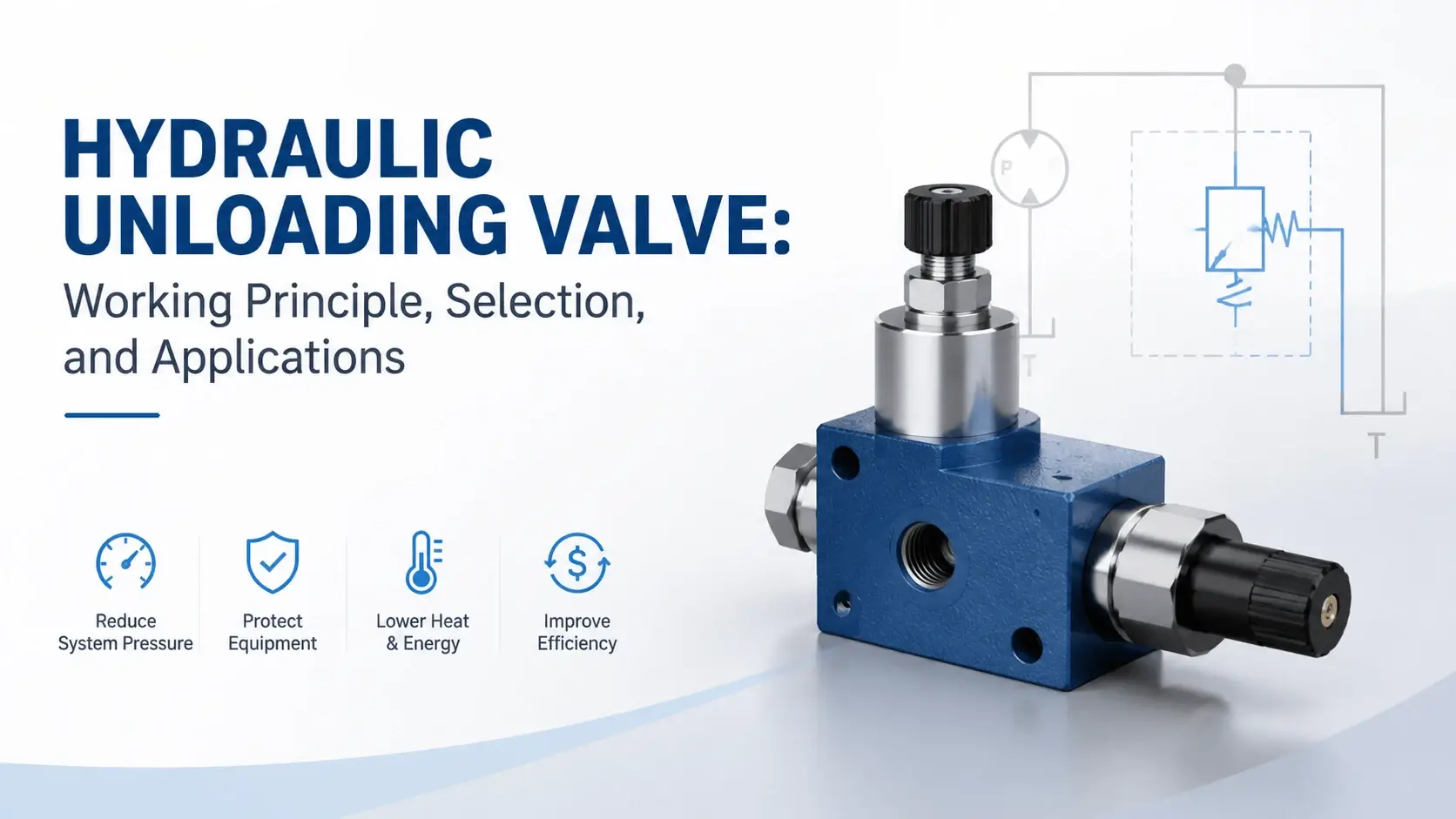
A hydraulic unloading valve saves energy. It dumps pump flow to the tank at near-zero pressure once the system reaches a set level. Instead of forcing fluid over a relief valve at full pressure, the pump runs light and cool. This guide explains how a hydraulic unloading valve works, where to place it, and how to choose the right one.
What is a Hydraulic Unloading Valve?
A hydraulic unloading valve is a pressure-control device. It redirects pump output to the reservoir when system pressure hits a preset cut-out point. The pump then runs unloaded, drawing little power and generating minimal heat. A check valve holds the pressurized fluid in the system while the pump rests.
The valve reloads the pump when pressure drops to a cut-in level. That difference between cut-out and cut-in creates a pressure band. The band prevents rapid on-off cycling and gives the system time to consume stored energy.
How a Hydraulic Unloading Valve Works
The mechanism relies on force balance. A spring holds a spool or poppet in the loading position. System pressure feeds a pilot line that pushes against the spring. When the pilot force exceeds the spring force, the spool shifts and opens a full-flow path to the tank.
At that point, the pump sees almost no resistance. Discharge pressure drops to a few bars, just enough to move oil through the return line. The check valve downstream closes and traps fluid at system pressure in the accumulator or cylinder.
When the system consumes enough fluid, pressure falls to cut-in. The pilot force drops below the spring force. The spool returns to the loading position. The pump builds pressure again until the next cut-out.
Unloading Valve vs Relief Valve
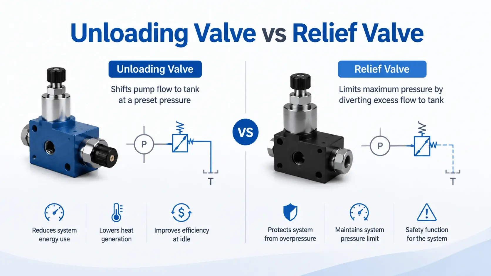
People mix these two up constantly. Both respond to pressure. Both route fluid flow to the tank. But they do very different jobs.
A relief valve cracks open at a set pressure. It passes excess flow while holding that pressure against the pump. The pump keeps working at full pressure the entire time. Every drop of bypassed fluid turns into heat.
An unloading valve takes a different path. Once it trips, the pump discharge drops to near tank pressure. A check valve holds system pressure while the pump coasts. Power consumption falls to 10 to 20 percent of loaded operation.
That difference shows up in the oil temperature. A system that unloads its pump runs 15 to 25 degrees C cooler. That beats a relief-only setup by a wide margin.
Accumulator Circuits
Accumulator systems are the most common home for an unloading valve. The pump charges the accumulator until pressure reaches the cut-out. The valve trips and unloads the pump. The accumulator then supplies fluid on demand.
This cycle repeats only when pressure bleeds down to cut-in. In a holding application, that might take minutes or hours. The pump sits idle most of the time, saving motor power and extending pump life.
The pressure differential sets the usable accumulator volume. A narrow 10 percent band gives stable pressure but short recharge intervals. A wider 20 to 30 percent band stores more fluid per cycle but lets pressure swing further. Most engineers settle on 15 to 20 percent for press and clamp circuits.
Hi-Lo Dual-Pump Circuits
A hi-lo circuit pairs two pumps. A large displacement pump delivers high flow for a fast approach. A small pump handles the high-pressure work stroke. The unloading valve ties them together.
At low pressure, both pumps deliver flow, and the actuator moves fast. When resistance builds and pressure hits the crossover point, the valve dumps the large pump to tank. Only the small pump continues, pressing at full force and lower flow.
This setup cuts motor size by 30 to 40 percent compared to a single large pump. Injection molding machines, presses, and compactor drives all rely on this arrangement.
The crossover pressure usually sits between 50 and 120 bar. Set it high enough for the large pump to aid the approach stroke. But set it low enough to unload before the motor draws full current.
Types of Unloading Valves
Three designs cover most applications.
Direct-acting unloading valves use a single spring and spool. They cost less and respond fast. Flow capacity tops out around 60 L/min. That makes them a good fit for small power units and auxiliary circuits.
Pilot-operated unloading valves add a small pilot stage that senses system pressure. The main spool opens fully once the pilot trips. This design handles 200 L/min and above with stable performance. Most industrial accumulator systems use this type.
Differential unloading valves use a piston with two opposing areas. System pressure acts on the smaller area to hold the valve closed. A remote pilot signal on the larger area forces it open. These appear in sequenced circuits where a separate control pressure triggers the unload.
Selecting the Right Unloading Valve
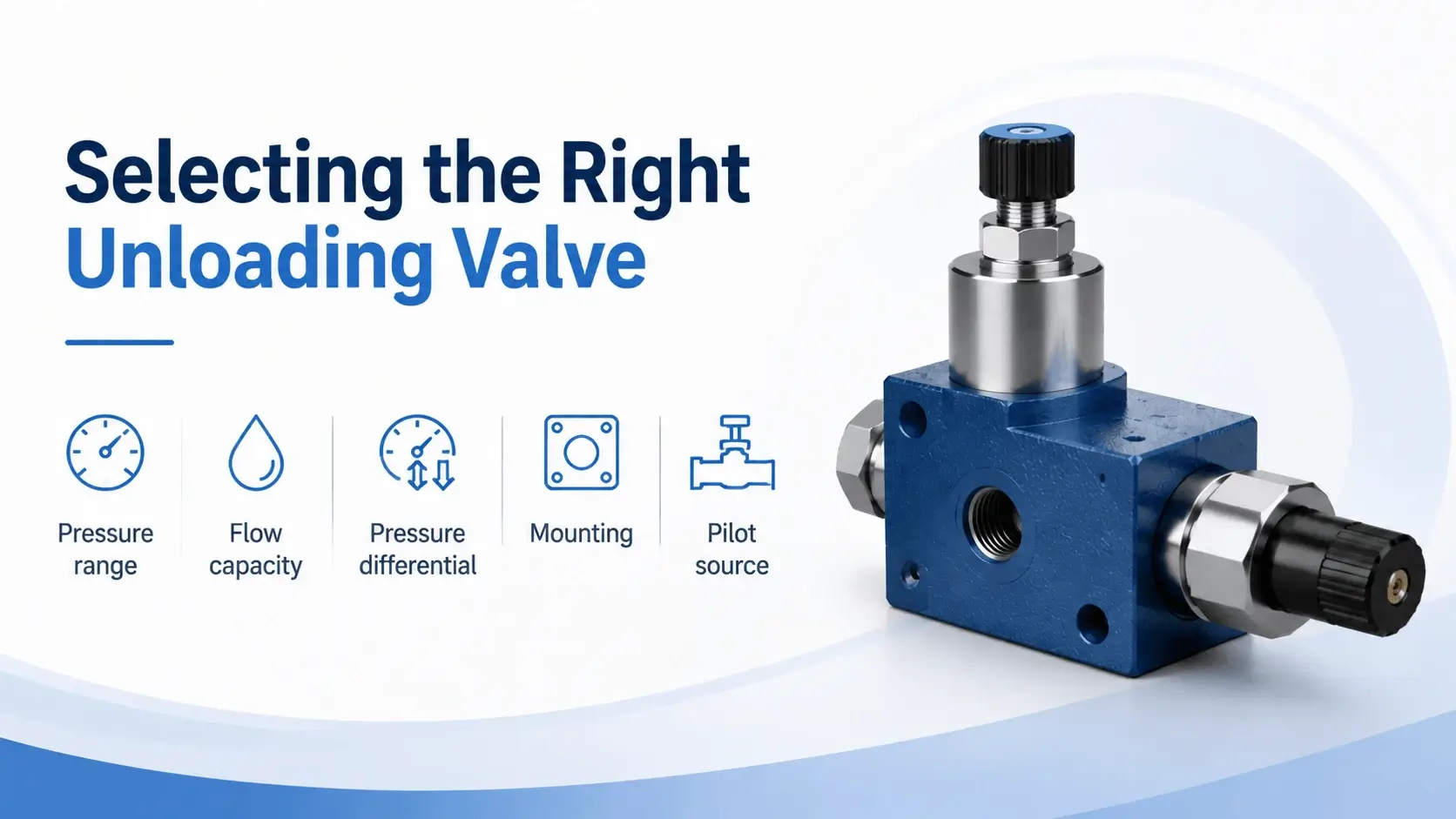
Work through these parameters before you order.
Pressure range
The cut-out pressure must cover your maximum system pressure. Most valves adjust from 30 to 350 bar. Pick a range that puts your set point in the middle third of the adjustment span for stable behavior.
Flow capacity
Size the valve for full pump flow, not average. An undersized valve chokes the return path and builds backpressure during unload.
Pressure differential
Factory differentials run 10 to 20 percent of cut-out. Fixed-differential valves suit steady-demand systems. Adjustable-differential valves fit applications with variable recharge cycles.
Mounting
ISO 4401 NG10 and NG16 patterns cover most industrial needs. Cartridge styles fit compact manifolds. Threaded bodies work for inline installations and mobile equipment.
Pilot source
Internal pilot valves sense their own inlet pressure. External pilot versions respond to a remote signal, useful when the unloading point differs from the valve location.
Common Problems and Troubleshooting
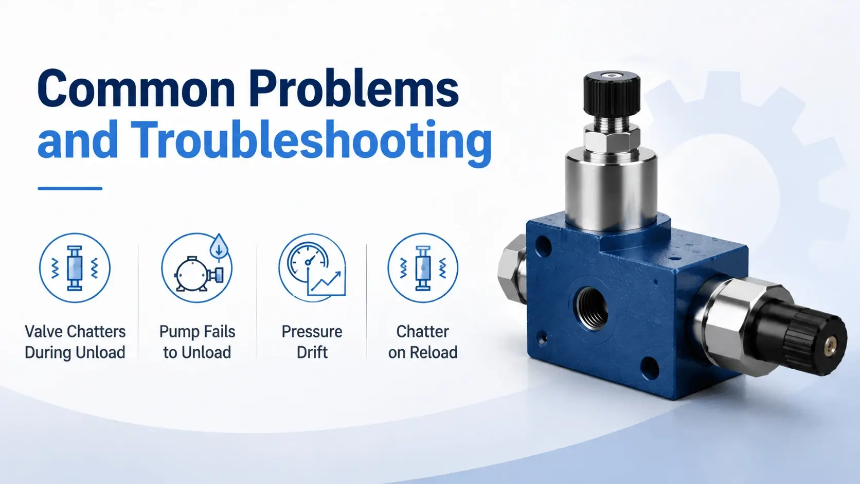
Valve Chatters During Unload
Rapid cycling between load and unload means the differential is too narrow. Widen the band by 5 to 10 percent. Also check for a weak or missing accumulator. That causes pressure to collapse instantly when the pump unloads.
Pump Fails to Unload
If the pump keeps building pressure past the cut-out point, check the pilot line for a blockage. Disconnect the pilot and blow it clear. A stuck spool from contamination produces the same symptom. Strip the valve, clean the bore, and verify ISO 4406 cleanliness at 18/16/13 or better.
Pressure Drift
Cut-out pressure that creeps over time points to spring fatigue or temperature change. Hydraulic oil thins as it warms. That shifts the effective setting by 5 to 8 percent across a 40 degree C swing. Recheck and readjust the setting after the system reaches operating temperature.
Chatter on Reload
If the valve slams back to load with a bang, the check valve may be sticking. A sluggish check valve lets system pressure bleed backward into the pump line. That causes the unloading valve to cycle. Inspect and clean the check valve seat and spring.
FAQ
What is a hydraulic unloading valve?
A hydraulic unloading valve routes pump flow to tank at near-zero pressure. It trips when system pressure reaches a preset level. A check valve holds system pressure while the pump rests. The valve reloads the pump when pressure falls to a cut-in level.
How does a hydraulic unloading valve work?
A spring holds the valve spool closed. A pilot line feeds system pressure against the spring. When pilot force beats spring force, the spool shifts and opens a full-flow path to tank. The pump unloads at low pressure. When system pressure drops to cut-in, the spring wins again and the valve reloads the pump.
What is the difference between an unloading valve and a relief valve?
A relief valve holds pump pressure at the set point while bypassing excess flow. The pump works at full pressure the whole time. An unloading valve dumps pump flow to tank at near-zero pressure once the system reaches full charge. The pump coasts while a check valve holds system pressure.
When should I use an unloading valve?
Use one when the pump can idle while the system holds pressure. Accumulator circuits, clamping systems, and hi-lo dual-pump setups all benefit. If your system needs continuous flow at full pressure, a relief valve is the better choice.
How do I adjust an unloading valve?
Loosen the locknut on the main spring adjuster. Turn clockwise to raise cut-out pressure, counterclockwise to lower it. Adjust the differential separately if your valve has that feature. Make changes in 10 bar steps with a gauge attached and the system at operating temperature.
Why does my unloading valve chatter?
Chatter usually means the pressure differential is too narrow. It can also point to a small or empty accumulator, or a sticking check valve. Widen the differential, verify accumulator precharge at 80 to 90 percent of cut-in, and inspect the check valve seat.
Conclusion
A hydraulic unloading valve cuts pump energy and heat whenever your system can hold pressure without continuous flow. Match the valve to your pump flow, set the differential to match your demand cycle, and pair it with a properly sized check valve. The result runs cooler, lasts longer, and draws less power than a relief-only setup.
Most field failures trace back to contamination, wrong differential settings, or a weak accumulator. Check the oil, verify the precharge, and confirm the cut-in and cut-out points with a gauge. Ten minutes of inspection per month keeps the circuit healthy.