
Introduction
Gear pumps fail. The gears score, the side plates wear, the shaft seal leaks, and the bearings go slack. When one fails on your power unit, loader, or press, you face a choice: gear pump repair or replacement. This guide covers both external and internal gear pump types from diagnosis through bench test.
Most gear pump repair jobs follow the same pattern. You notice low flow, noise, or leakage. You pull the pump. You open it up and find scored teeth, worn side plates, or a grooved shaft. The question is whether the damage sits within rebuild limits or past them. This article gives you the limits, the measurements, and the procedures to make that call correctly.
When Gear Pump Repair Makes Sense (and When It Does Not)
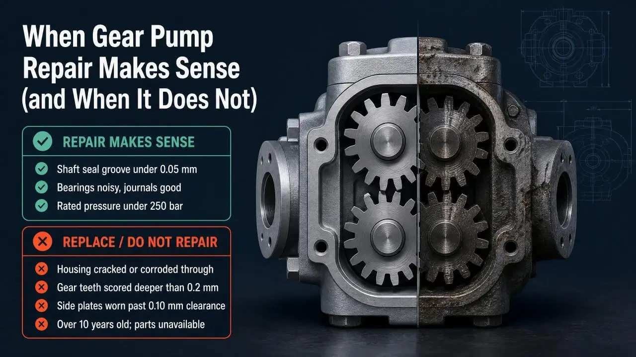
Not every failed gear pump earns a rebuild. A cracked housing goes straight to recycling. A set of gears with deep scoring across every tooth belongs in the scrap bin. But a pump with worn side plates, tired bearings, and a leaking shaft seal often costs less to rebuild than to replace.
Use this decision matrix before you commit hours:
| Condition | Verdict |
|---|---|
Housing cracked or corroded through |
Replace |
Gear teeth scored deeper than 0.2 mm |
Replace |
Side plates worn past 0.10 mm clearance |
Rebuild with new plates |
Shaft seal groove under 0.05 mm |
Rebuild, replace seal |
Bearings noisy but journals good |
Rebuild, replace bearings |
Pump under 250 bar rated pressure |
Usually worth rebuilding |
Pump over 10 years old, parts unavailable |
Replace |
Cost drives most decisions here. A small gear pump rebuild (under 20 L/min) runs 200 to 600 in parts and labor. A mid-size unit (20 to 100 L/min) runs 500 to 1,800. Compare those numbers against a new pump price. If parts and labor exceed 55 percent of new, buy new. If the pump is critical and lead time matters, buy new now and rebuild the old unit as a spare.
How Gear Pumps Fail: Failure Mode Reference
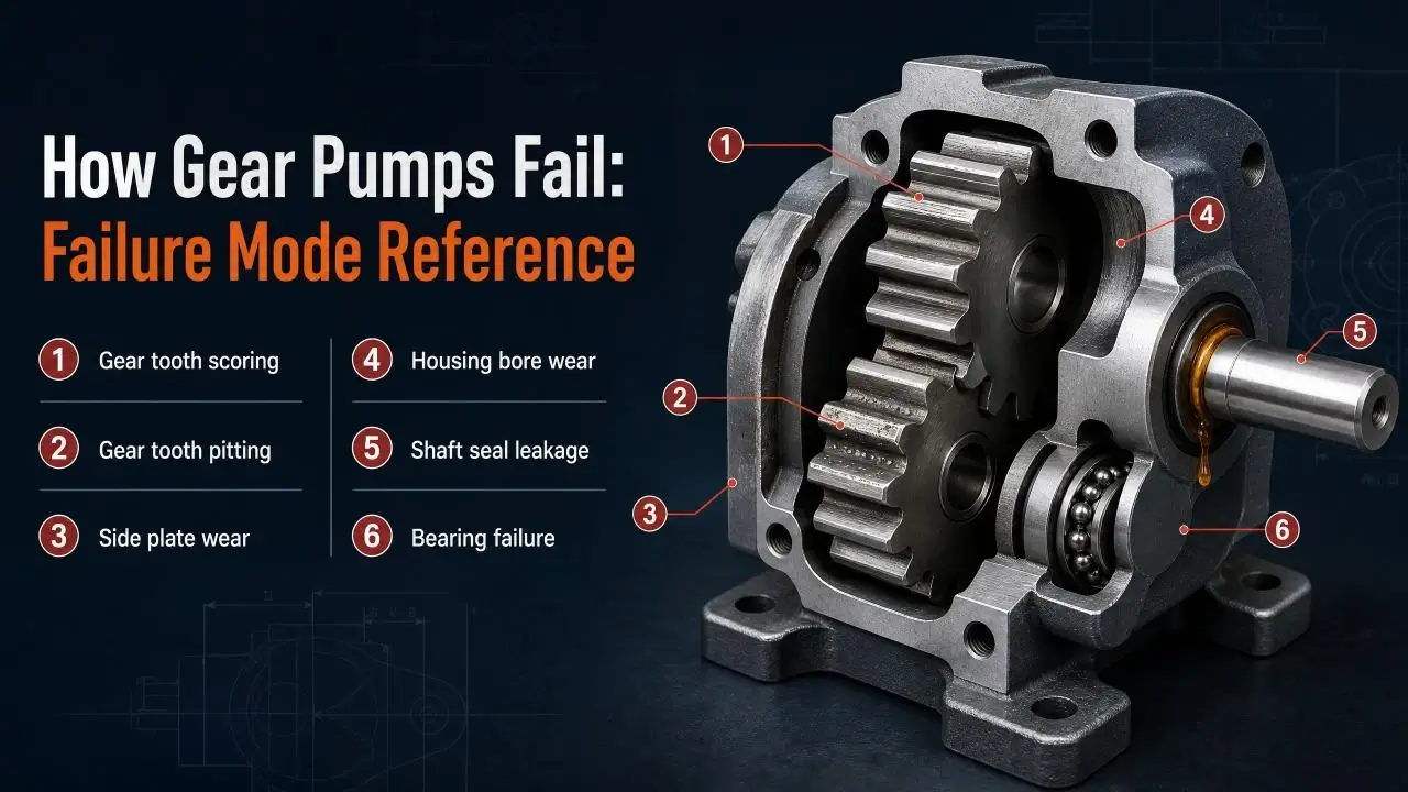
Gear pumps fail in predictable ways. Contamination causes most failures. A single particle of steel grit caught between a gear tooth and the housing scores both surfaces. That scoring increases clearance. Increased clearance drops flow and heats the oil. Hot oil degrades faster. Degraded oil carries less contamination away. The cycle accelerates until the pump cannot hold pressure.
These are the six failure modes you will see on the bench:
| Failure Mode | What You See | Root Cause |
|---|---|---|
Gear tooth scoring |
Parallel scratches on tooth flanks |
Hard particle ingestion |
Gear tooth pitting |
Craters on tooth faces |
Cavitation or fatigue |
Side plate wear |
Step wear pattern on plate faces |
Normal wear accelerated by contamination |
Housing bore wear |
Out-of-round or oversize bore |
Abrasive particles in oil |
Shaft seal leakage |
Oil at shaft exit point |
Seal age, shaft groove, or high case pressure |
Bearing failure |
Noise, shaft play, heat |
Misalignment, overload, or contamination |
The failure mode tells you the scope of the gear pump repair. Scoring and pitting on gears usually mean replacement. Side plate wear and seal leakage mean a standard rebuild. Bearing failure means you check the shaft and housing bores before you order parts.
Pre-Teardown Diagnosis: Test Before You Open
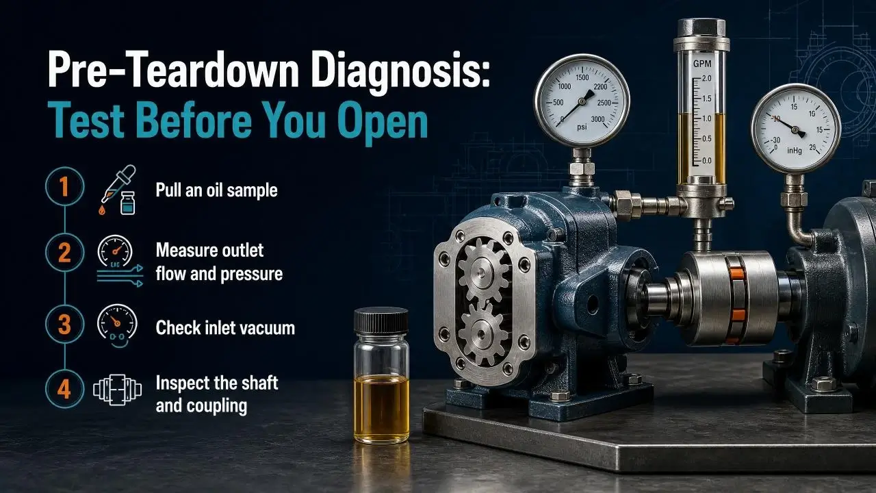
Diagnosis first. Tearing down a pump without test data destroys evidence. The oil inside the case tells you what killed the pump. The flow reading at the outlet tells you how much efficiency the pump lost. Skip these steps and you rebuild blind.
Pull an oil sample
Drain a small amount of oil from the case drain port while the pump runs. Send it to a lab for particle count and elemental analysis. High silicon means dust got in. High iron means iron components wore. High copper means a bearing is failing. The lab report points you toward the root cause before you open the housing.
Measure outlet flow and pressure
Tee a flow meter and pressure gauge into the pump outlet line. Run the pump at rated speed and compare readings against the nameplate. Flow below 85 percent of nominal at rated pressure means internal leakage has crossed into rebuild territory. Pressure that builds slowly or oscillates points to worn gears or damaged side plates.
Check inlet vacuum
Fit a vacuum gauge at the pump inlet. Anything above 0.15 bar vacuum at full flow signals a restriction. Check the strainer, suction hose, and reservoir level. Cavitation from restricted inlet scores gear teeth and side plates. Fix the inlet before you finish the gear pump repair or the new parts wear just as fast as the old ones.
Inspect the shaft and coupling
Check shaft runout with a dial indicator. Above 0.04 mm runout means bearing wear or a bent shaft. Look at the coupling too. Misalignment loads the bearings unevenly and cuts shaft seal life by half or more. Correct alignment before the rebuilt pump goes back into service.
External Gear Pump Repair Procedure
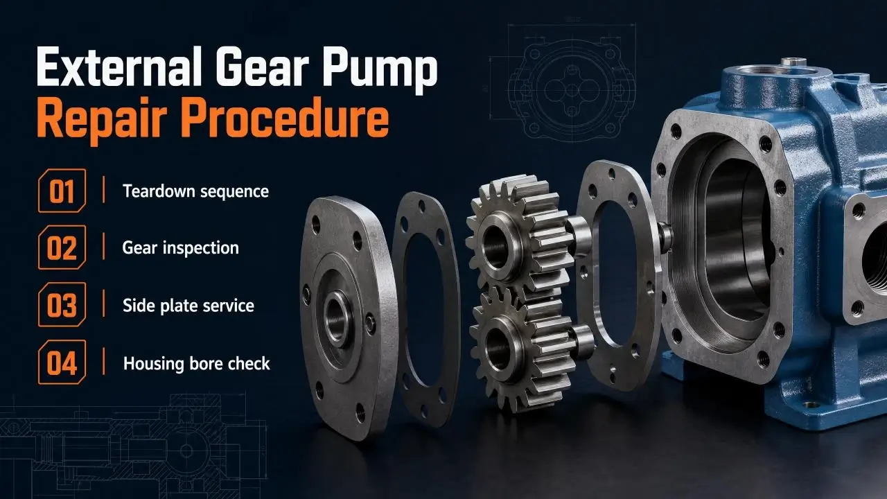
External gear pumps use two meshing gears inside a close-fitting housing. The drive gear connects to the input shaft. The driven gear rides on a pin or bushing in the front or rear cover. Side plates seal the axial ends of the gears. Those four components account for 95 percent of all external gear pump service work.
Teardown sequence
Lock out the power source. Drain the oil. Remove the inlet and outlet ports. Mark the cover orientation relative to the housing with a punch or scribe. Remove the cover bolts and lift off the cover.
Pull the drive gear and driven gear together. Note which gear face contacted which side plate. Some pumps have different clearance patterns on the inlet and outlet sides. Mark the gears so they return to the same mesh orientation. Running gears in a different mesh position accelerates wear on unmatched tooth profiles.
Inspect each component against the tolerance table later in this article. Photograph the scoring patterns. They tell the story of how the pump failed.
Gear inspection
Lay the gears on a clean surface under good light. Check every tooth flank for scoring parallel to the pitch line. That pattern means hard particles passed through the mesh. Check the tooth tips for rounding and the tooth roots for pitting. Pitting comes from cavitation fatigue or oil starvation.
Measure gear tooth thickness with a gear tooth caliper or micrometer over pins. Compare against the original spec. Tooth wear above 0.05 mm on the pitch diameter reduces volumetric efficiency noticeably. Above 0.10 mm, replace the gear set.
Side plate service
Side plates take more abuse than any other component in an external gear pump. They seal the gear ends against housing pressure. Any gap between the gear face and the side plate lets oil leak from the outlet back to inlet.
Measure side plate thickness with a micrometer at four or more points around the plate. A new plate shows uniform thickness within 0.005 mm. A worn plate shows a step pattern: thinner near the outlet ports where pressure forces the gear against the plate. Thickness variation above 0.03 mm means replacement.
Check the plate surface for scoring. Light scoring under 0.01 mm deep can be removed by lapping on a granite surface plate with 5 micron compound. Deep scoring means discard and replace. Never install a scored side plate. It leaks from day one.
Housing bore check
The housing bore holds the gears at a running clearance that typically ranges from 0.02 to 0.06 mm on diameter when new. As abrasive particles pass through, the bore wears into an oval or hourglass shape.
Measure the bore with a dial bore gauge at three positions: top, middle, and bottom of the gear sweep area. Rotate the gauge 90 degrees and measure again. Out-of-round above 0.03 mm means the housing has worn past acceptable limits. An oversized bore, even if round, above 0.08 mm over nominal diameter also means replacement.
A housing that passes bore inspection gets a cleanup. Polish light scoring with fine abrasive cloth. Remove any burrs from the cover mating surface. Blow out debris with filtered compressed air.
Internal Gear Pump Repair Procedure
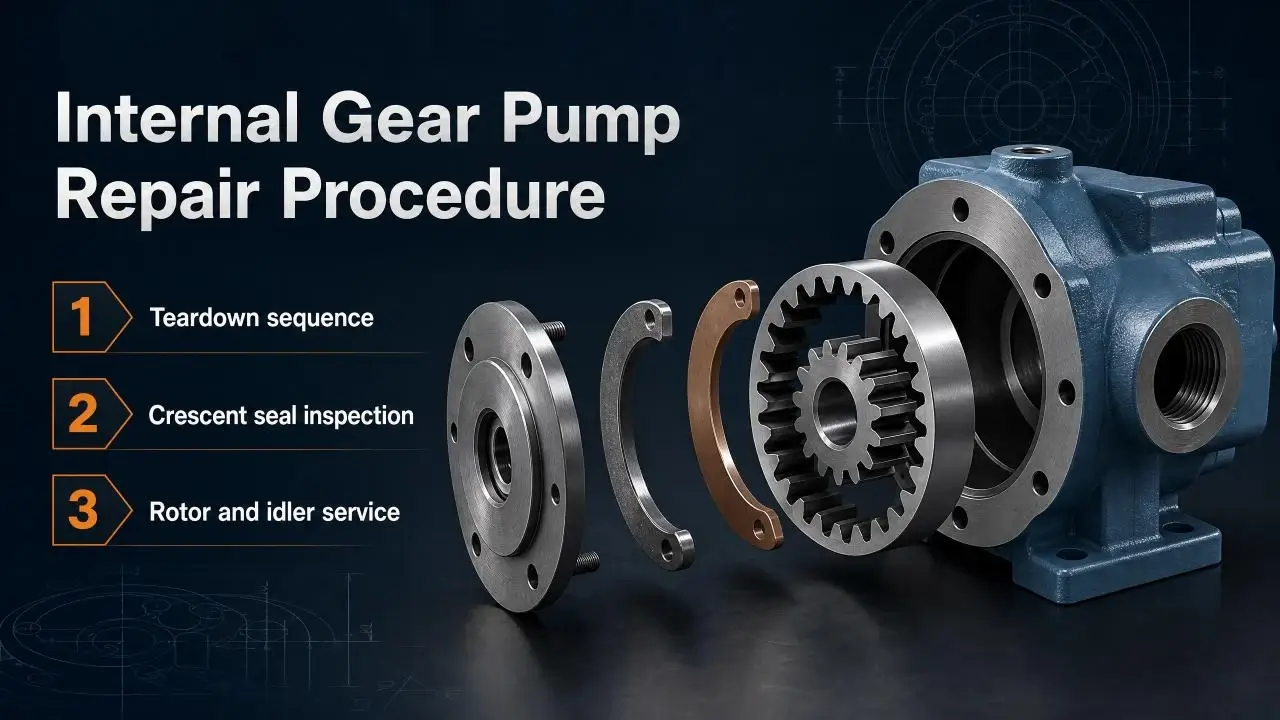
Internal gear pumps use a cogged inner gear (rotor) meshing with an outer ring gear inside a housing. A crescent-shaped seal fills the space between the gears at the inlet and outlet zones. The crescent, the rotor, the idler gear or ring, and the shaft seal account for most internal gear pump service work.
Teardown sequence
Follow the same lockout and drain procedure as the external pump. Remove the cover bolts and lift the cover. In most designs, the cover holds the shaft bearing and seal. The rotor and crescent come out with the cover on some designs. On others they stay in the body. Check the manufacturer’s exploded view before you pull parts.
Remove the crescent seal carefully. It is often a soft material like carbon-filled PTFE or bronze. Handle it by the edges. Fingerprints on the sealing surface hold contaminants that cause leaks.
Pull the rotor and inspect the drive splines or keyway. Check the idler gear or outer ring for tooth wear. Note which face of each part seals against which mating surface.
Crescent seal inspection
The crescent seal separates the inlet zone from the outlet zone. Wear on the crescent tip allows high-pressure oil to leak directly back to the inlet. That kills volumetric efficiency faster than almost any other wear mode in an internal gear pump.
Measure the crescent tip thickness with a micrometer. Compare against the minimum spec, usually 90 percent of new thickness. A thin or stepped crescent gets replaced. Never reuse a crescent with visible scoring or edge damage.
Check the crescent slot in the cover or body for wear. If the slot walls show scoring or the crescent fits loosely, the slot may need machining or the cover may need replacement.
Rotor and idler service
Inspect the rotor teeth for the same scoring and pitting patterns described for external gears. Internal gear pumps run at lower pressures, so tooth wear tends to progress slower. But contamination still scores the teeth.
Check the idler pin or bushing where the idler gear rotates. A worn pin lets the idler wobble. Wobble loads the crescent unevenly and wears a step into the tip. Measure pin diameter against spec. Replace the pin and idler bushing as a set if wear exceeds 0.02 mm.
Critical Measurements and Tolerance Limits
These numbers separate a successful gear pump repair from a repeat failure. Write them on your bench checklist. Measure every part against these limits before you order new ones.
| Component | Measurement | New Spec | Rebuild Limit | Scrap Threshold |
|---|---|---|---|---|
Gear tooth thickness |
Micrometer over pins |
Per drawing |
-0.05 mm |
-0.10 mm |
Side plate thickness |
Micrometer, 4+ points |
Uniform +/- 0.005 mm |
Variation < 0.03 mm |
Variation > 0.03 mm or deep scoring |
Side plate flatness |
Straight edge + feeler |
< 0.005 mm |
< 0.01 mm after lapping |
> 0.01 mm |
Housing bore ID |
Dial bore gauge |
Nominal + 0.02-0.06 mm |
Out-of-round < 0.03 mm |
Out-of-round > 0.03 mm or > +0.08 mm |
Shaft journal under seal |
Micrometer |
Per drawing |
Groove < 0.05 mm |
Groove > 0.05 mm |
Shaft runout |
Dial indicator |
< 0.02 mm |
< 0.04 mm |
> 0.04 mm |
Bearing axial play |
Dial indicator |
Per bearing spec |
Within spec |
Outside spec |
Crescent tip thickness |
Micrometer |
Per drawing |
> 90% of new |
< 90% of new |
Idler pin diameter |
Micrometer |
Per drawing |
-0.02 mm |
> -0.02 mm |
When a part falls between the rebuild limit and the scrap threshold, the call depends on pump criticality and parts availability. A non-critical pump with cheap parts gets fresh components. A critical pump with long lead time parts might earn a risky rebuild with a shorter expected service life. Document that decision.
Reassembly: The Steps That Kill Rebuilds
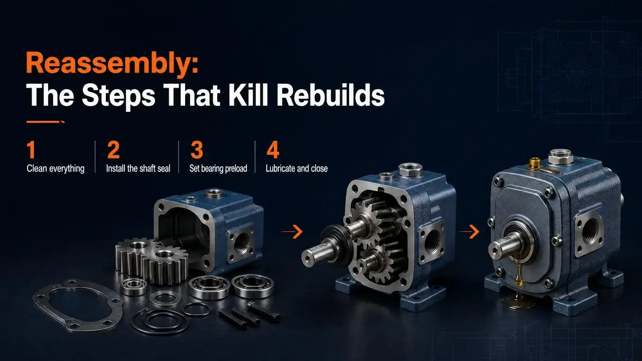
Reassembly is where most gear pump repair jobs go wrong. Clean conditions, correct torque, proper lubrication, and bearing preload determine whether the rebuilt pump runs for years or fails in weeks.
Clean everything
Wash every part in solvent. Blow dry with filtered air. Lay parts on clean paper towels on a clean bench. A single grain of sand between a side plate and the gear face starts the wear cycle again. If your bench is not clean enough to eat off, it is not clean enough for gear pump reassembly.
Install the shaft seal
Replace the shaft seal on every gear pump repair. No exceptions. The seal costs under ten dollars in most sizes. A failed seal dumps oil onto the machine frame, creates a slip hazard, and pulls the pump out of service.
Inspect the shaft journal under the lip. A groove deeper than 0.05 mm requires a speedi sleeve or a new shaft. Install the sleeve with Loctite or the recommended adhesive. Trim the sleeve end flush after the adhesive cures.
Lightly coat the seal lip with system oil before installation. Press the seal in square using a seal driver or a socket that matches the OD. A cocked seal leaks immediately. Verify the seal orientation: lip toward the oil for single-lip seals.
Set bearing preload
Most external gear pumps use tapered roller bearings or angular contact ball bearings on the shaft. These bearings require a specific preload value. Too loose and the shaft moves under load, loading one side plate harder than the other. Too tight and the bearing overheats and fails.
Set preload with a dial indicator on the shaft end. Snug the cover bolts while watching the indicator. Stop at the specified axial play or preload value. Most gear pumps call for 0.02 to 0.08 mm axial play after preload. Check the manufacturer’s manual for your specific model.
Torque the cover bolts in a star pattern. Use a calibrated torque wrench. Uneven torque warps the side plates and creates leakage paths.
Lubricate and close
Coat the gears, side plates, and bearings with clean hydraulic oil before assembly. Dry assembly scars parts during the first seconds of operation. Install the cover with the orientation marks aligned. Torque the bolts to spec.
Post-Rebuild Testing Protocol
A rebuilt gear pump proves itself on a test stand. Without a test stand, you install an unproven pump and hope for the best. Hope is not a reliability strategy.
Bench test setup
Mount the pump on a test stand with a variable-speed drive, a relief valve, a flow meter, a pressure gauge, and a temperature gauge. Fill the reservoir with clean hydraulic oil at ISO 4406 18/16/13 or better. Connect the case drain line to tank, unrestricted.
Run the pump at no load for ten minutes. Watch the case temperature. A rise above 15 degrees C over ambient means a bearing drags or the side plates rub. Stop and find the problem.
Pressure and flow test
Bring the relief valve up in stages. Hold 25 percent of rated pressure for three minutes. Hold 50 percent for three minutes. Hold 75 percent for three minutes. Hold full rated pressure for ten minutes.
Record flow at each pressure stage. A properly rebuilt gear pump delivers 95 to 100 percent of nominal flow at rated pressure. Flow below 90 percent means a leakage path remains. Check the side plate seals, the housing bore clearance, and the shaft seal seating.
Listen for noise throughout the test. A whine at high pressure suggests cavitation or air ingestion. A knocking or grinding sound means metal-to-metal contact. Shut down immediately and investigate.
Leak check
Wipe down the pump exterior with clean rags. Run at rated pressure for five minutes. Inspect the shaft seal, cover gasket, and port fittings for weepage. A slight film at the shaft seal during break-in is normal. Active dripping means the seal installed wrong, the shaft has a groove, or case pressure runs too high.
Common Gear Pump Repair Mistakes
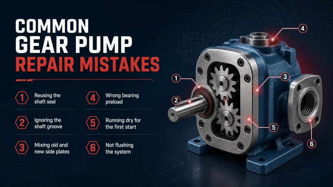
These mistakes cause repeat failures. Learn them once and avoid them forever.
Reusing the shaft seal
It failed once. It will fail again. Ten dollars now saves a teardown later.
Ignoring the shaft groove
A new seal in a grooved shaft lasts days, not weeks. Measure the groove. Install a sleeve or replace the shaft.
Skipping the housing bore measurement. A worn bore lets the gears walk. Walking gears load one side of the side plates and wear a step into them. Measure the bore. If it is out-of-round, scrap the housing.
Mixing old and new side plates
One new plate and one worn plate create uneven clearance. The gear tips load the thinner plate and wear it fast. Replace side plates as a pair.
Wrong bearing preload
A loose shaft wanders and kills the seal. A tight bearing overheats and seizes. Use a dial indicator. Follow the spec.
Running dry for the first start
Oil coats the parts during assembly but burns off before the pump turns. Prime the pump with oil before the first start. Run at no load until circulation confirms.
Not flushing the system
The same dirty oil that killed the old pump waits in the reservoir for the rebuilt one. Flush the system. Change the filters. Refill with clean oil.
FAQ
How much does gear pump repair cost?
A small gear pump under 20 L/min displacement costs 200 to 600 to rebuild. Parts run 40 to 50 percent of that total. Labor makes up the rest. Mid-size pumps from 20 to 100 L/min run 500 to 1,800. Large gear pumps above 100 L/min can hit $3,000 depending on housing condition and gear availability. Compare the quote against a new pump price. If the rebuild exceeds 55 percent of new, replacement usually wins unless lead time is the constraint.
How long does a gear pump rebuild take?
Most external gear pump rebuilds complete in 4 to 8 working hours plus test time. Internal gear pumps take 5 to 10 hours due to the extra service points. Add time for parts ordering if you do not stock side plates, seals, and bearings. Add half a day if the housing needs bore measurement and evaluation. A shop with parts in stock can turn a standard gear pump repair around in two to three days.
Can you repair a gear pump yourself?
Yes, if you have a clean workbench, a press, a torque wrench, a dial indicator, a micrometer set, and a test stand. The procedures are straightforward compared to piston pump work. The tolerances are looser. The risk is skipping a measurement and missing a part that should have been replaced. If you lack a test stand, send the pump out for commissioning. A pump that has not been tested is a question mark, not a solution.
What causes gear pump failure most often?
Contamination. Studies from fluid power labs consistently rank particle contamination as the number one cause of gear pump failure. Dirt enters through breathers, open reservoirs, and loose fittings. Once inside, hard particles score gear flanks, wear side plates, and ovalize housing bores. Cavitation from restricted inlets ranks second. Seal aging and misalignment rank third. Fix the contamination source or every gear pump repair becomes a temporary fix.
How do I know if my gear pump is bad?
Five signs. First, slow actuator speed at normal system pressure. Second, a whine or rumble that changes with load. Third, oil temperature running 10 degrees C or more above normal operating range. Fourth, visible leakage at the shaft or cover gasket. Fifth, gradual pressure drop over days or weeks that the relief valve cannot compensate for. Confirm with a flow test at the outlet. Flow below 85 percent of nameplate at rated pressure means the pump needs gear pump repair or replacement.
Conclusion
Gear pump repair succeeds when you measure before you tear down, replace parts that sit outside tolerance limits, reassemble with clean conditions and correct preload, and prove the result on a test stand. It fails when you swap the obvious parts and ignore the measurements that reveal why the pump failed in the first place.
The difference between a rebuild that lasts two years and one that lasts two months lives in the details. Measure the side plate thickness. Check the housing bore for out-of-round. Inspect the shaft under the seal lip. Set bearing preload with a dial indicator, not by feel.
Flush the system before the rebuilt pump goes back online. Test the pump before it leaves the bench.
If your gear pump has failed and you need help deciding between repair and replacement, or if you want a second opinion on a rebuild quote, the measurements in this article give you the framework to evaluate options with real numbers.