
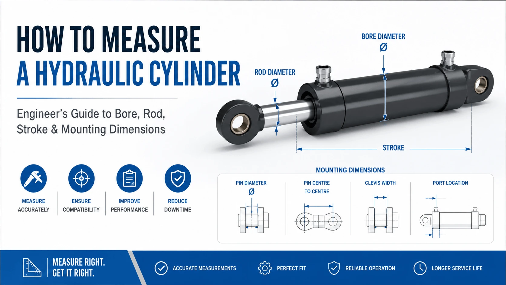
Why Getting It Right Matters
How to Measure a Hydraulic Cylinder: Tools You Need
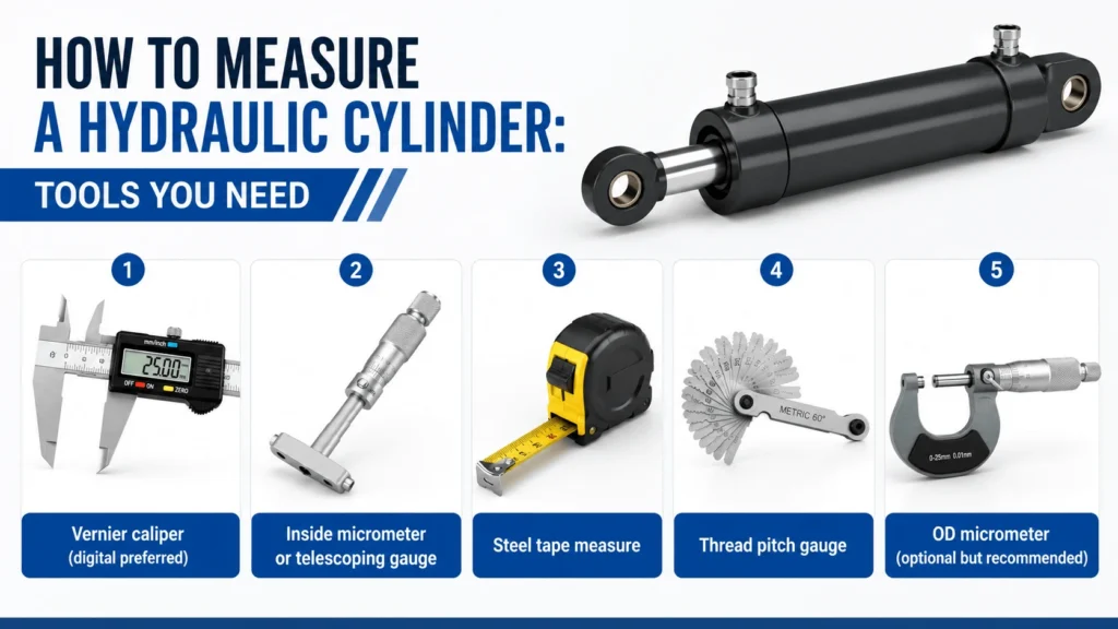
| Tool | Used For | Typical Range |
|---|---|---|
Vernier caliper (digital preferred) |
Rod OD, barrel OD, pin diameters, gland dimensions |
0–150 mm / 0–6″ |
Inside micrometer or telescoping gauge |
Bore ID |
25–200+ mm |
Steel tape measure |
Stroke, overall lengths, C-to-C distances |
3–5 m |
Thread pitch gauge |
Port thread identification |
Metric + imperial |
OD micrometer (optional but recommended) |
Rod diameter accuracy check |
0–75 mm |
Measuring the Bore Diameter
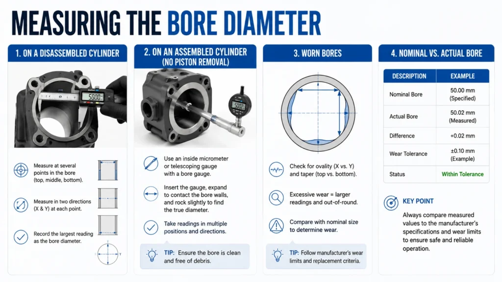
The bore is the single most critical dimension. It determines the cylinder’s force output at any given system pressure. Measure it wrong and everything downstream is off.
On a Disassembled Cylinder
If you have the piston out, insert a telescoping gauge into the barrel. Expand it gently until the tips contact the wall. Lock it, remove it, and read the dimension with a micrometer or caliper. Take readings at three locations along the barrel length: near the gland end, midpoint, and blind end. Record all three. A new cylinder should vary less than 0.02 mm (0.0008″) across its length. Anything beyond that indicates barrel out-of-roundness or taper from wear.
On an Assembled Cylinder (No Piston Removal)
Most field measurements happen with the cylinder intact. You have two options here:
- Measure through the rod-end gland opening if the rod is fully retracted. Use a small telescoping gauge or inside caliper. Reach past the rod and feel for the barrel wall.
- Measure the piston rod and work backward. If you know the nominal area ratio (typically 2:1 or 1.5:1 for standard double-acting cylinders), estimate the bore from the rod area. This is approximate but useful when disassembly is impossible.
Worn Bores
Here is a hard truth: a worn cylinder measures larger than its original bore. Scoring, corrosion, and abrasive wear add material loss. If you measure 102.3 mm on a cylinder marked “100 mm bore,” that extra 2.3 mm tells you the seal lip has lost support. Do not just order another 100 mm bore cylinder and hope the same seals last longer. Specify the actual measured bore to your seal supplier, and decide whether the barrel needs re-boring or replacement.
Nominal vs. Actual Bore
Hydraulic cylinder bores follow standard size series (ISO 4399 / NFPA T3.6). Common bore sizes in millimeters are 25, 32, 40, 50, 63, 80, 100, 125, 140, 160, 180, 200, 220, 250. In inches: 1″, 1.5″, 2″, 2.5″, 3″, 4″, 5″, 6″, 8″. A brand-new ISO 100 mm bore cylinder will actually measure between 100.02 and 100.08 mm depending on the manufacturer’s tolerance class (commonly H8 or H9 per ISO 286). When you order a replacement, quote the nominal size first, then note your actual measurement as a reference.
Measuring the Piston Rod Diameter
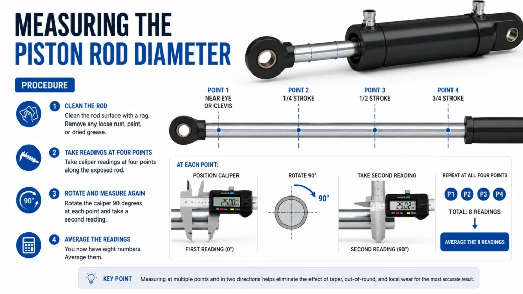
The rod takes the entire load in tension during retraction. Its diameter affects retract force, buckling strength, and seal compatibility.
Procedure
Clean the rod surface with a rag. Remove any loose rust, paint, or dried grease. Take caliper readings at four points along the exposed rod: near the eye or clevis, 1/4 stroke, 1/2 stroke, and 3/4 stroke. Rotate the caliper 90 degrees at each point and take a second reading. You now have eight numbers. Average them.
What to Look For
- Taper: If the rod diameter decreases by more than 0.05 mm toward the eye end, the rod has worn unevenly, probably from misalignment or side loading.
- Scoring: Deep longitudinal scratches catch seal lips. Run a fingernail along the rod surface. If you feel a ridge, that rod needs grinding or replacement regardless of the diameter reading.
- Chrome layer thickness: Hard chrome plating on rods is typically 0.02–0.05 mm thick. If your measurements show the rod is undersized by more than that relative to the nominal spec, the base steel may be exposed.
Standard Rod Sizes
Rod diameters correlate to bore size. Below is a quick reference for common ISO/NFPA combinations:
| Bore (mm) | Typical Rod (mm) | Area Ratio (Extend : Retract) |
|---|---|---|
40 |
20, 22 |
~1.3:1, ~1.6:1 |
50 |
25, 28 |
~1.3:1, ~1.7:1 |
63 |
32, 36, 45 |
~1.35:1, ~1.5:1, ~2:1 |
80 |
40, 45, 56 |
~1.33:1, ~1.46:1, ~2:1 |
100 |
50, 56, 70 |
~1.33:1, ~1.46:1, ~2:1 |
125 |
63, 70, 90 |
~1.34:1, ~1.46:1, ~2.1:1 |
160 |
80, 90, 110 |
~1.33:1, ~1.46:1, ~2:1 |
200 |
100, 110, 140 |
~1.33:1, ~1.49:1, ~2:1 |
The area ratio matters because the retract force equals pressure times (bore area minus rod area). A 100 mm bore with a 70 mm rod delivers roughly half the retract force compared to the extend force at the same pressure.
Measuring Stroke Length
Stroke seems simple until you realize there are three different “stroke” definitions floating around the industry, and suppliers sometimes mean different things by each.
Definition: Stroke
Stroke = the total linear distance the piston travels from fully retracted to fully extended. That is the textbook definition. But in practice, you must also know:
- Usable stroke: Travel distance available for your application after accounting for internal cushions, stop tubes, or mechanical limits.
- Maximum mechanical stroke: The absolute limit before the piston contacts the gland or blind end cap.
How to Measure
- Fully retract the cylinder. Mark the rod position at the gland face or at a fixed reference point on the machine frame.
- Fully extend the cylinder (be careful not to bottom out hard against the end cap). Mark the rod again.
- Measure the distance between marks. That is your stroke.
If the cylinder is still mounted and you cannot fully extend it, measure the retracted length first, then extend to your normal operating position and measure again. Subtract. Add 10–15% margin for the remaining hidden travel unless you know the exact mechanical stop point.
Stop Tubes and Cushions
Some cylinders have an internal stop tube (a spacer between the piston and gland) that reduces effective stroke to prevent side-loading damage. Others have adjustable cushion plungers that rob 10–30 mm of travel at each end. Neither is visible from outside. If your measured stroke does not match the nameplate spec, a stop tube or cushion may explain the difference.
Overall Cylinder Lengths
Suppliers ask for two lengths: retracted (closed center) and extended (open center).
Retracted Length (CL)
With the cylinder closed, measure from the center of the rear mounting feature to the center of the rod-end mounting feature. For clevis mounts, that means pin center to pin center. For flange mounts, use the flange face. For trunnion mounts, use the trunnion journal centerline.
Write this down as CL = [value].
Extended Length (OL)
Fully extend the cylinder and repeat the same center-to-center measurement. Write it as OL = [value].
You can verify your math: OL should equal CL + stroke (within a few millimeters, depending on the piston width). If OL is significantly shorter than CL + stroke, you may have incomplete extension or a stop tube you did not account for.
Mounting Style and Pin Dimensions
A cylinder with the right bore and wrong mount is useless. Identify the mount type and measure the associated hardware.
Common Mounting Styles
| Mount Style | Description | Typical Application |
|---|---|---|
Clevis (double ear) |
U-shaped yoke with cross-pin |
Mobile equipment, excavator arms |
Clevis (single ear) |
Single lug with through-pin |
Light-duty linkages |
Trunnion |
Pivot journals mounted mid-barrel or at caps |
Articulated loaders, cranes |
Flange (rectangular/square) |
Bolt pattern on end cap |
Industrial presses, machine tools |
Tang / Eye |
Threaded rod eye with spherical bearing |
Linear actuators, small cylinders |
Foot / Lug |
Mounting lugs on barrel or cap side |
Fixed industrial installations |
Pin Diameter and Tolerance
Measure the mounting pin diameter with a caliper. Check the pin holes in the clevis ears or trunnion brackets, too. Note any ovalization. Worn pin holes become egg-shaped over time. If the hole is 0.3 mm wider than the pin, plan for bushing replacement or oversize pin procurement.
Pin fits matter. A loose pin accelerates wear on the cylinder mounts and transfers side loads into the rod and gland seals. Standard practice for clevis pins in heavy-duty applications is ISO f7/h6 clearance fit (roughly 0.02–0.06 mm diametral clearance for pins up to 50 mm). If your pin rattles freely in the hole, something is already worn out.
Port Size and Thread Identification
Cylinders have at least two fluid ports (blind end and rod end). Some have drain ports, cushion adjustment ports, or position-transducer fittings. You need to match every one of them on the replacement.
Step-by-Step Port Identification
- Locate all ports on the barrel and/or end caps. Count them.
- Measure the thread major diameter with calipers. For external threads on the port boss, measure across the crests. For internal threads, measure the root diameter at the opening.
- Use a thread pitch gauge to determine the pitch (metric) or threads-per-inch (imperial)
Match to a known standard:
| Standard | Common Sizes (Cylinders) | Pitch/TPI Examples |
|---|---|---|
BSPP (BSP parallel) |
1/8″, 1/4″, 3/8″, 1/2″, 3/4″, 1″ |
28 TPI (small), 19 TPI (medium), 14 TPI (large), 11 TPI (1″+) |
BSPT (BSP tapered) |
Same sizes as BSPP |
Same TPI values, but tapered seat |
NPT (tapered pipe) |
1/8″, 1/4″, 3/8″, 1/2″, 3/4″, 1″ |
27 TPI (up to 1/2″), 14 TPI (3/4″ and up) |
Metric (M) |
M12×1.5, M14×1.5, M16×1.5, M18×1.5, M22×1.5, M27×2, M33×2 |
Pitch in mm |
If you lack a thread gauge, try screwing a known fitting into the port. A G 1/2 BSPP fitting will not hand-tighten into a 1/2 NPT port. The angle is different. Do not force it.
Seal Groove Measurements (When Rebuilding)
If you plan to rebuild rather than replace, you need seal groove dimensions. This requires partial disassembly: at a minimum, the gland nut must come off.
Gland Seals
The rod sealing gland typically holds:
- A wiper/seal scraper (exposed face)
- A rod seal (U-cup, piston seal, or buffer seal)
- One or two backup rings (anti-extrusion rings)
- Sometimes a bearing band
Measure the groove ID (where the seal lip sits against the rod) and groove width (axial depth). Compare these to the seal catalog from your supplier (Parker, Hallite, SKF, Trelleborg). Most standard grooves follow DIN ISO 5597 or ISO 7425 profiles. If your groove matches a standard profile, you only need the nominal rod diameter and pressure rating to select seals. If the groove is non-standard (common on older OEM equipment), you will need custom seals or a machined gland replacement.
Piston Seals
Piston seals sit in grooves machined into the piston body. To measure them, the piston must come out. Once it is out, record groove OD (against the barrel wall), groove ID (around the piston core), and groove width. Double-acting pistons often have two symmetrical seal grooves, one on each face.
Cross-Check Your Measurements With a Force Calculation
This step separates careful technicians from careless ones. After you write down all dimensions, run a quick calculation:
Extend Force (theoretical) = Pressure (bar or psi) × Bore Area
Retract Force (theoretical) = Pressure × (Bore Area − Rod Area)
Compare the result to your machine’s known working load or the old cylinder’s nameplate rating (if legible). If your calculated force at 210 bar (3,000 psi) comes out to 45 kN but the lift mechanism is rated for 120 kN, either your bore measurement is wrong, the system operates at a higher pressure than you assumed, or the cylinder was never properly sized for this job.
Example Calculation
Measured bore: 100 mm → Area = π × (100/2)^2 = 7,854 mm^2System pressure: 210 bar (21 MPa)Extend force = 21 MPa × 7,854 mm^2 = 164,934 N ≈ 165 kN (about 37,000 lbf)Rod diameter: 56 mm → Rod area = 2,463 mm^2Annular area (retract) = 7,854 – 2,463 = 5,391 mm^2Retract force = 21 MPa × 5,391 mm^2 = 113,211 N ≈ 113 kN (about 25,400 lbf)
If the machine datasheet says the cylinder should produce 180 kN extension force, your 165 kN number suggests either higher operating pressure (maybe 230 bar) or the original cylinder had a slightly larger bore (105 mm). Either way, you now have data to discuss with your supplier instead of guessing.
Common Measurement Mistakes
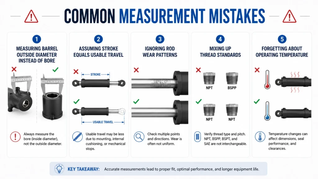
1. Measuring Barrel Outside Diameter Instead of Bore
2. Assuming Stroke Equals Usable Travel
3. Ignoring Rod Wear Patterns
4. Mixing Up Thread Standards
5. Forgetting About Operating Temperature
Ordering a Replacement: Spec Sheet Template
CYLINDER REPLACEMENT REQUESTApplication: [machine type, e.g., Komatsu PC200 excavator – boom cylinder]Operating Pressure: ____ bar / ____ psiBore Diameter: ____ mm (nominal) / ____ mm (measured)Rod Diameter: ____ mm (nominal) / ____ mm (measured)Stroke Length: ____ mmRetracted Center-to-Center: ____ mmMounting Style: [clevis/trunnion/flange/tang]Rear Mount Details: [pin dia ___ mm, ear spacing ___ mm]Rod End Mount Details: [pin dia ___ mm, eye/clevis ID ___ mm]Port Threads: [e.g., G 1/2 BSPP x 2 ports, M18x1.5 drain]Seal Material Preference: [nitrile/polyurethane/Viton] if knownQuantity: ____Delivery Location: ________Notes: [any special conditions – high temp, corrosive environment, etc.]