
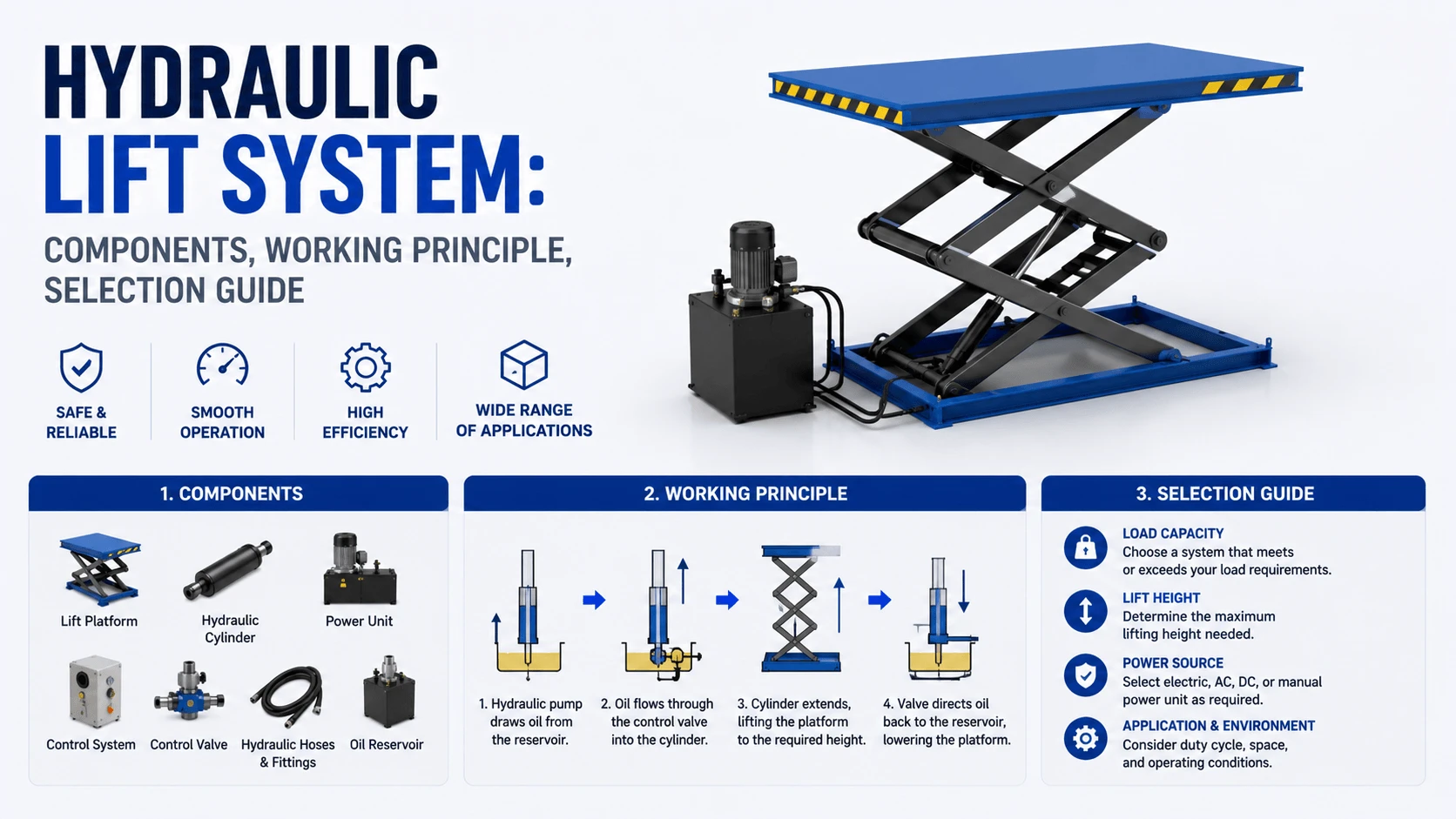
What Is a Hydraulic Lift System?
How a Hydraulic Lift System Works
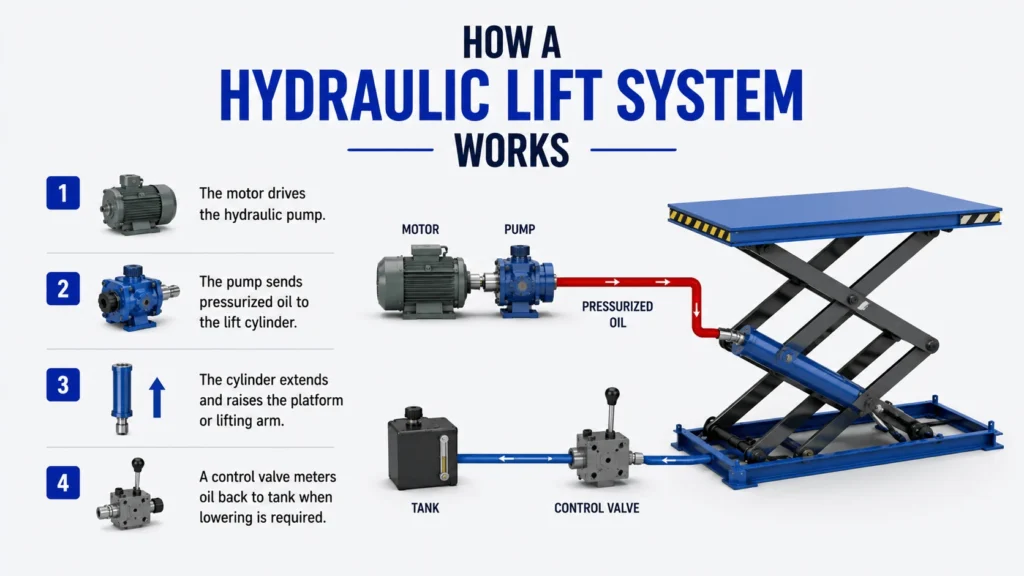
A typical hydraulic lift cycle has four stages:
- The motor drives the hydraulic pump.
- The pump sends pressurized oil to the lift cylinder.
- The cylinder extends and raises the platform or lifting arm.
- A control valve meters oil back to the tank when lowering is required.
For safe operation, the system must also control overload, uncontrolled descent, hose failure, and thermal expansion. That is where relief valves, check valves, counterbalance valves, velocity fuses, and mechanical locks become important.
Main Components of a Hydraulic Lift System
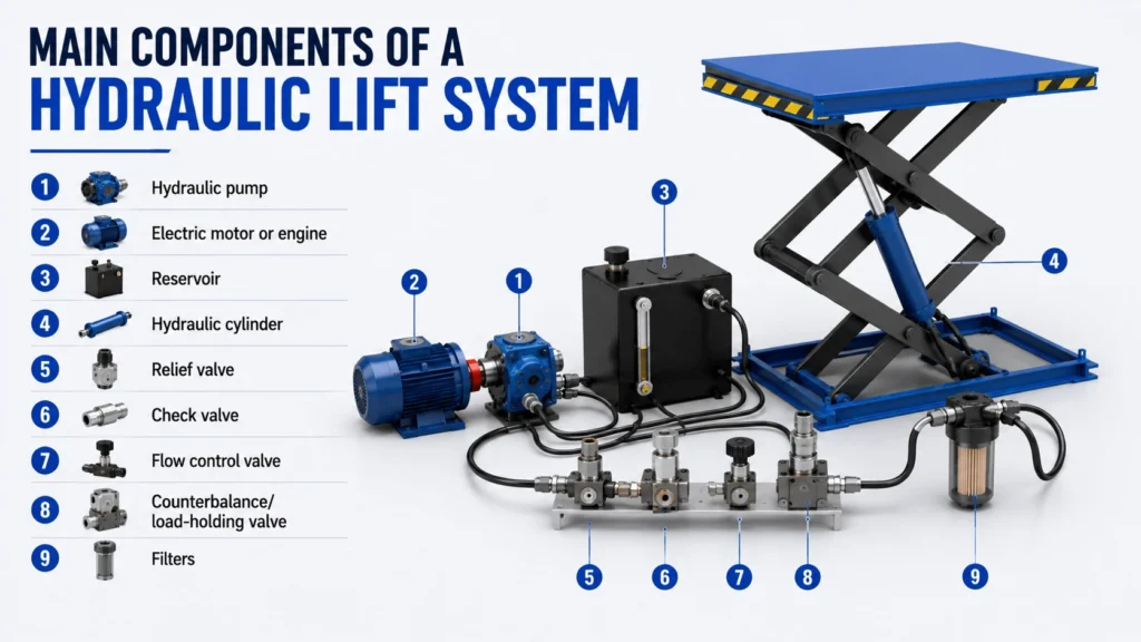
| Component | Function | Engineering Notes |
|---|---|---|
Hydraulic pump |
Converts mechanical power into oil flow |
Gear pumps are common for simple lifts; piston pumps suit higher efficiency or variable flow systems |
Electric motor or engine |
Drives the pump |
Motor sizing must match pressure, flow, duty cycle, and starting load |
Reservoir |
Stores hydraulic oil |
Should allow heat dissipation, air separation, and contamination control |
Hydraulic cylinder |
Converts pressure into lifting force |
Bore, rod size, stroke, mounting, and buckling risk must be checked |
Relief valve |
Limits maximum pressure |
Protects pump, hoses, valves, and structure from overload |
Check valve |
Holds oil in the cylinder |
Prevents reverse flow when the pump stops |
Flow control valve |
Controls lifting or lowering speed |
Pressure-compensated types give more stable speed under changing load |
Counterbalance/load-holding valve |
Prevents runaway lowering |
Important for elevated loads and hose-failure protection |
Filters |
Remove contamination |
Contamination is one of the most common causes of valve and cylinder failure |
Typical Pressure and Flow Ranges
Small shop lifts and light-duty platforms often operate around 1,500 to 3,000 psi. Many mobile and industrial hydraulic lift systems operate near 2,500 to 3,500 psi. Heavy-duty or compact high-force systems may use higher pressure, but hose rating, cylinder design, seals, valves, and safety factor must all match the selected pressure.
Flow rate determines speed. Small lifts may use only a few gallons per minute, while large industrial lifts or synchronized multi-cylinder platforms may require 20 GPM, 50 GPM, or more. Oversizing flow increases speed, but it also raises heat generation, energy consumption, noise, and control difficulty.
Advantages of Hydraulic Lift Systems
Hydraulic lift systems offer high force density, smooth movement, good overload protection, and flexible layout. Cylinders can be placed where mechanical screw or chain drives would be difficult to install.
They also handle dirty, wet, and heavy-duty environments better than many electromechanical systems. For applications such as dock lifts, dump tables, foundry equipment, vehicle lifts, and maintenance platforms, hydraulics are often the practical choice.
Disadvantages and Limitations
Hydraulic systems require oil cleanliness, seal maintenance, leak control, and proper temperature management. A poorly maintained system may drift, lower unevenly, overheat, or lose lifting capacity.
Efficiency is also load- and design-dependent. A simple fixed-displacement gear pump is cost-effective, but it may waste energy if the system spends long periods at pressure without useful motion. Variable displacement pumps, unloading circuits, or power-on-demand designs can improve efficiency in higher-duty applications.
Industrial Applications
Hydraulic lift systems are used in:
- Scissor lift tables
- Vehicle service lifts
- Freight elevators and goods lifts
- Dock levelers and dock lifts
- Material handling platforms
- Dumping and tilting equipment
- Aerospace and rail maintenance platforms
- Manufacturing assembly lines
- Heavy equipment service stands
For personnel lifting or elevator-type applications, local codes and safety standards become especially important. For example, elevator and similar vertical transportation systems may fall under ASME A17.1/CSA B44 requirements depending on jurisdiction and application.
Common Hydraulic Lift Problems
| Problem | Likely Causes | Practical Checks |
|---|---|---|
Lift will not raise |
Low oil level, worn pump, relief valve stuck open, overloaded platform |
Check oil level, pressure gauge reading, pump noise, load weight |
Lift raises slowly |
Low flow, clogged filter, worn pump, high oil viscosity |
Check filter, oil temperature, pump output, motor speed |
Lift drifts down |
Internal cylinder leakage, leaking check valve, faulty load-holding valve |
Isolate cylinder and valve sections to locate leakage path |
Jerky movement |
Air in oil, contamination, sticking valve, poor lubrication |
Bleed system, inspect oil condition, check suction leaks |
Overheating |
Excessive bypassing, undersized reservoir, high duty cycle, wrong oil viscosity |
Measure oil temperature and pressure drop across valves |
Uneven lifting |
Cylinder imbalance, structural binding, poor synchronization |
Inspect guides, pins, cylinder flow division, platform alignment |
Noise or cavitation |
Restricted suction line, low oil, wrong viscosity, pump wear |
Check suction strainer, oil level, inlet hose condition |
Troubleshooting Guide
How to Select a Hydraulic Lift System
| Selection Factor | What to Confirm |
|---|---|
Rated load |
Include load weight, off-center loading, fixtures, and safety factor |
Lift height and stroke |
Match cylinder stroke and platform geometry |
Duty cycle |
Occasional lifting needs a different power unit than continuous production use |
Speed requirement |
Determines pump flow and valve sizing |
Available power |
Electric voltage, phase, engine drive, or battery power |
Environment |
Dust, water, outdoor exposure, temperature, corrosion risk |
Safety requirements |
Mechanical locks, hose burst protection, overload protection, emergency lowering |
Maintenance access |
Filter, reservoir, valves, cylinder pins, and hoses should be reachable |
Compliance needs |
ISO 4413, ANSI/ALI, ASME, OSHA, or local authority requirements where applicable |
For procurement, do not compare hydraulic lifts only by rated capacity. Ask for cylinder bore, working pressure, pump type, valve configuration, hose rating, lowering control method, documentation, and recommended inspection interval.
Maintenance Tips
Good maintenance is mostly about oil cleanliness, leak control, and safety inspection.
Recommended checks include:
- Inspect hoses, fittings, and cylinders for leakage.
- Check the reservoir oil level and oil condition.
- Replace filters according to service interval or differential pressure.
- Inspect cylinder rods for scoring, corrosion, or seal damage.
- Verify relief valve and load-holding valve operation.
- Check platform pins, bushings, welds, anchors, and mechanical locks.
- Keep the lift clean, so leaks and structural damage are visible.
- Record inspection, repair, and oil-change history.
For vehicle lifts, the Automotive Lift Institute recommends at least annual inspection by a qualified lift inspector. OSHA also notes that employers remain responsible for recognized workplace hazards even where no lift-specific OSHA standard applies.
FAQs
What is a hydraulic lift system?
A hydraulic lift system is a machine that uses pressurized oil and one or more hydraulic cylinders to raise, lower, and hold a load.
How does a hydraulic lift system work?
A pump sends pressurized oil into a cylinder. The pressure acts on the piston area, creating a lifting force. Valves control direction, speed, overload protection, and load holding.
What pressure does a hydraulic lift system use?
Many light and industrial lift systems operate between 1,500 and 3,500 psi, but the correct pressure depends on load, cylinder size, structure, duty cycle, and safety requirements.
Why does a hydraulic lift drift down?
Common causes include internal cylinder leakage, a leaking check valve, contamination in the valve seat, or a faulty counterbalance/load-holding valve.
Is a gear pump or a piston pump better for hydraulic lifts?
A gear pump is simple, economical, and common for basic lifts. A piston pump is better for higher pressure, variable flow, better efficiency, or demanding duty cycles.
Authority Sources
- ISO 4413 hydraulic fluid power safety requirements
- OSHA interpretation on automotive service lifts
- Automotive Lift Institute annual lift inspection guidance
- ANSI/ALI automotive lift standards information
- ASME A17.1 elevator and escalator safety code overview
Need a hydraulic lift system for industrial equipment, vehicle service, material handling, or custom machinery? Contact our engineering team with your load capacity, lift height, duty cycle, power supply, and working environment. We can help specify the hydraulic cylinder, power unit, valves, and safety configuration for your application.