
Hydraulic Shock: Causes, Damage, and Proven Fixes

Hydraulic Shock- Causes, Damage, and Proven Fixes

Table of Contents

Hydraulic shock is a sudden pressure surge inside a hydraulic system. It happens when moving oil stops or changes direction faster than the system can absorb. The spike can reach two to four times normal working pressure in milliseconds.

That spike travels through the line as a pressure wave. It slams into hoses, seals, gauges, and valve seats. One event may only startle the operator. Repeated events fatigue every component they touch.

This guide explains the physics in plain terms, shows how to measure a spike correctly, and gives four field-proven control methods. The numbers come from real systems running at 210 to 350 bar.

What is Hydraulic Shock?

Hydraulic shock is a transient pressure wave generated when fluid velocity changes abruptly in a closed line. Engineers also call it water hammer or pressure surge. A fast valve closure, a cylinder hitting the end of stroke, or an emergency stop can all trigger it.

In a typical industrial system, oil flows at 2 to 6 m/s through a rigid pipe. Stop that flow in 30 milliseconds, and the line sees a sharp overpressure. The wave bounces between the valve and the pump until friction dissipates it.

Plumbing articles treat water hammer as a noise problem. In hydraulics, the stakes are higher. Working pressures run 10 to 40 times greater than in a water line, so the same physics produces far more destructive peaks.

The Physics Behind a Pressure Spike

The Joukowsky equation predicts the spike magnitude. Pressure rise equals fluid density times wave speed times velocity change.

For mineral oil at roughly 870 kg/m3 with a wave speed near 1,200 m/s in rigid steel pipe, stopping 1 m/s of flow adds about 10 bar. Stop 4 m/s instantly and the line gains roughly 40 bar on top of working pressure.

Real systems behave worse than the formula suggests. Three factors push peaks higher:

  • Fast valve response. A direct-acting solenoid valve closes in 20 to 50 milliseconds, fast enough to count as instant closure.
  • Hose sections. Wave speed drops to 300 to 600 m/s in a hose, which stretches the event and adds vibration.
  • Trapped air. Aerated oil compresses unevenly and amplifies the wave.

A 210 bar press circuit can briefly see 400 bar or more. The pump never produced that pressure. The moving oil did.


Common Causes of Pressure Surges
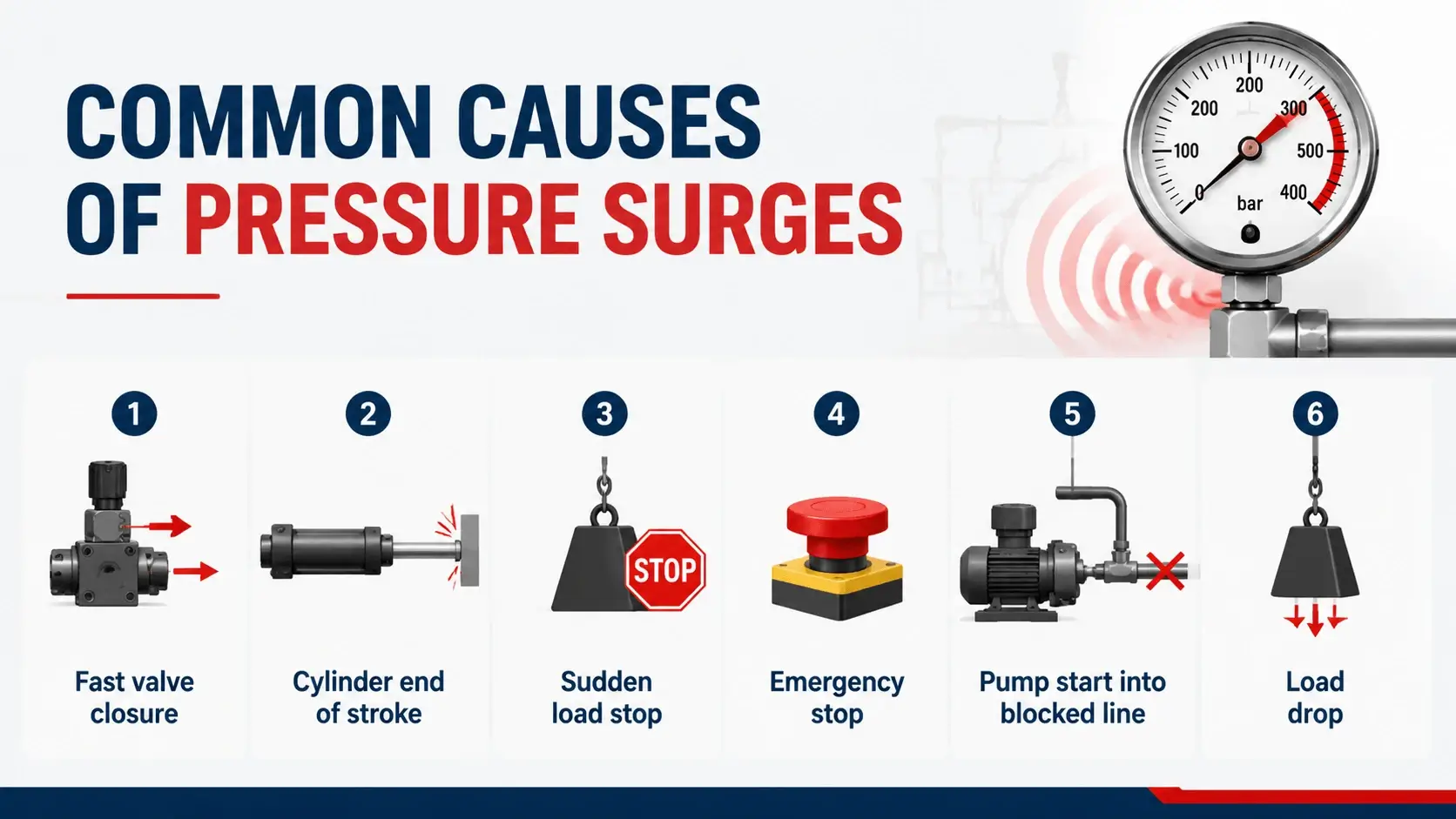
Common Causes of Pressure Surges
Cause Typical Trigger Spike Severity
Fast valve closure
Solenoid de-energizes in 20 to 50 ms
High
Cylinder end of stroke
Piston stops against cap without cushioning
High
Sudden load stop
Load hits a mechanical stop or stalls
Medium to high
Emergency stop
All actuators halt at once
Medium
Pump start into blocked line
Dead-headed start before valve opens
Medium
Load drop
Brake or counterbalance fails to hold
High
The pattern is consistent. Any event that changes oil velocity in tens of milliseconds will generate a pressure spike. Slow events do not, because the system has time to move the energy elsewhere.

What Pressure Spikes Damage

The pressure wave attacks the weakest points first. Field failures cluster in a predictable order.
 
Hoses take the first hit. Repeated spikes fatigue the wire braid and cause weeping at the fittings long before the rated impulse life expires. Seals extrude when a spike exceeds the extrusion gap allowance, even if the average pressure stays in spec.
 
Mechanical gauges suffer quietly. The Bourdon tube sees peaks far above its scale, and the gauge loses calibration within months. Fittings loosen under vibration. Accumulator bladders tear when spikes arrive faster than the gas side can respond.
 
Relief valves chatter and wear their seats. The seat damage then causes leakage at normal pressure, which technicians often misdiagnose as a bad valve rather than a symptom of repeated surges.

How to Detect and Measure Pressure Spikes

You cannot see a spike on a standard pressure gauge. A mechanical gauge responds in 100 milliseconds or more, while the event finishes in 5 to 20 milliseconds. The needle barely twitches.
 
Use a pressure transducer with at least 1 kHz sampling. For serious analysis, sample at 5 to 10 kHz and mount the sensor close to the suspected source. A portable data logger captures the peak, the rise time, and the wave shape.
 
Listen for field clues first. A loud bang at valve shift, hoses that jump at every cycle, and recurring leaks at the same fitting all point to pressure surges. Confirm with a transducer before spending money on hardware.

Four Proven Ways to Control Hydraulic Shock

1. Slow the Event Down

The cheapest fix is time. Proportional and soft-shift directional valves ramp the spool over 100 to 1,000 milliseconds instead of snapping open or shut. Ramp controls on modern amplifiers do the same job electronically.
 
Cylinder cushioning handles end-of-stroke events. A built-in cushion meters oil through a small orifice in the last 15 to 25 mm of travel and converts kinetic energy into heat. For heavy loads, add meter-out flow control or deceleration valves.

2. Absorb the Spike With an Accumulator

A bladder accumulator mounted close to the shock source absorbs the wave before it travels far. Set nitrogen precharge at 80 to 90 percent of the minimum working pressure. Lower precharge makes the bladder bottom out. Higher precharge leaves no room to accept oil.
 
Response speed matters here. Bladder designs react fast enough for shock duty. Piston accumulators respond more slowly and suit energy storage better. Keep the connecting line short, straight, and at least as large as the accumulator port.

3. Relieve the Peak Locally

Direct-acting relief valves open in a few milliseconds, fast enough to clip short spikes. Pilot-operated reliefs respond too slowly for this job.
 
On hydraulic motors, fit crossline relief valves across the two ports. When a valve slams shut, the oil leaving the motor has nowhere to go. The crossline pair relieves the high side and feeds the low side, which prevents both the spike and cavitation. Anti-shock and anti-cavitation cartridge valves package this function for manifolds.

4. Strengthen What Remains

After you reduce the spike, upgrade the survivors. Choose a hose with an impulse rating that matches the real cycle profile on the datasheet, not just the working pressure. Avoid sharp 90 degree fittings near the valve outlet. Use proper clamping so lines cannot whip.
 
Check that relief settings, gauge ranges, and sensor ratings tolerate the residual peak. A gauge rated at 1.5 times working pressure will still fail if the real peak hits 3 times.

Troubleshooting Guide

Symptom Likely Cause First Fix
Bang at every valve shift
Solenoid valve too fast
Add ramping or soft-shift valve
Spike at cylinder end of stroke
No cushion or worn cushion
Adjust or rebuild cushion
Hoses leaking at same fitting
Repeated surge at that branch
Accumulator near source
Gauge drift or failure
Peaks above gauge range
Snubber plus higher range gauge
Relief valve seat leakage
Chatter from repeated spikes
Direct-acting relief, fix root cause
Motor seal failure after stop
Blocked outlet on deceleration
Crossline relief valve
Treat the gauge drift and seat leakage as evidence, not as the disease. Replacing parts without slowing the event guarantees repeat failures.

FAQ

What is hydraulic shock in simple terms?

Hydraulic shock is a sudden pressure surge that occurs when moving oil stops or reverses faster than the system can absorb. The spike can reach two to four times normal working pressure and damages hoses, seals, gauges, and valve seats over time.

What causes hydraulic shock?

The main causes are fast solenoid valve closure, cylinders reaching end of stroke without cushioning, sudden load stops, emergency stops, and pump starts into blocked lines. Anything that changes oil velocity within tens of milliseconds can trigger a surge.

How do you stop hydraulic shock?

Four methods work in the field. Slow the event with proportional valves or ramping. Absorb the spike with a bladder accumulator precharged to 80 to 90 percent of working pressure. Clip peaks with direct-acting or crossline relief valves. Then upgrade hose and fittings to handle what remains.

How much pressure can a spike add?

In rigid steel pipe with mineral oil, stopping 1 m/s of flow adds about 10 bar on top of working pressure. Real peaks in fast-switching systems often reach two to four times working pressure, so a 210 bar circuit can briefly see over 400 bar.

Why does my gauge not show the pressure spike?

A mechanical gauge needs 100 milliseconds or more to respond, but a shock event finishes in 5 to 20 milliseconds. The gauge averages the peak away. Use a pressure transducer sampling at 1 kHz or faster to capture the true spike.

Does an accumulator always fix water hammer?

No. An accumulator works only when sized and precharged correctly and mounted close to the source. Wrong precharge, long connecting lines, or a slow piston design will leave the spike largely untouched. Combine absorption with slower valve action for reliable control.

Conclusion

Hydraulic shock is a physics problem with a predictable price tag. The Joukowsky equation tells you how big the spike can get, and a fast transducer tells you how big it actually is.
 
Start by slowing the event, since ramping and cushioning cost little and remove most of the energy. Add a correctly precharged accumulator near the source, protect motors with crossline relief, and upgrade the hardware that still sees peaks.
 
Systems built or retrofitted this way stop eating hoses and gauges. The noise disappears, leaks dry up, and component life returns to what the datasheets promised.

Related Articles

Scroll to Top
Shoot Us An Email

Professional Manufacturer