
Introduction
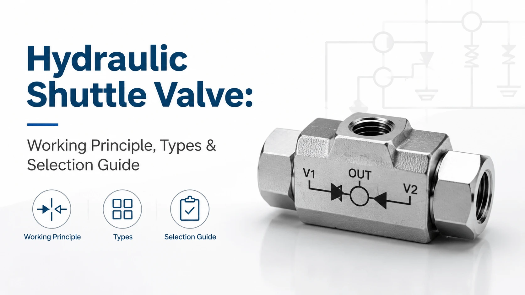
Many hydraulic circuits need to select automatically between two pressure sources without solenoids, levers, or controllers. A hydraulic shuttle valve does exactly that. It passes whichever inlet has the higher pressure and blocks the lower one.
This guide covers shuttle valve mechanics, design types, sizing, and the circuits where these components earn their place. We focus on real engineering data: cracking pressures, leakage specs, cleanliness targets, and the cross-line relief application that accounts for most industrial shuttle valve usage.
What is a Hydraulic Shuttle Valve
A hydraulic shuttle valve is a three-port, two-position valve that automatically routes fluid from the higher of two inlet ports to a single outlet port. It works like two check valves mounted back-to-back inside one body.
Engineers also call this component a double check valve, OR valve, or automatic selector valve. The ISO 1219 symbol shows two check valve symbols arranged in opposition with a shared outlet.
The valve has no external actuator. Pressure differential alone moves the internal sealing element. Whichever inlet pressurizes first, or whichever runs at a higher pressure, opens its path to the outlet. The other inlet seals off.
How a Hydraulic Shuttle Valve Works
Flow enters both inlet ports at different pressures. Inside the body, a movable sealing element sits between them. When inlet A exceeds inlet B plus the cracking pressure, the element shifts toward B. Inlet A connects to the outlet.
When inlet B rises above inlet A, the element shifts the opposite way. Inlet B now feeds the outlet and inlet A blocks. The valve switches continuously as pressures change. No operator input required.
The cracking pressure determines the minimum differential needed to shift the element. Most industrial shuttle valves crack open at 0.3 to 1.0 bar. Low cracking pressure minimizes energy loss but can cause dithering when both inputs run nearly equal. Higher cracking pressure adds stability at the cost of slightly more pressure drop.
Ball Type vs Poppet Type Design
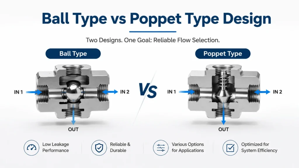
Shuttle valves use one of two internal designs. Each has distinct characteristics.
Ball Type Shuttle Valves
A hardened steel ball sits between two tapered seats. Pressure pushes the ball against the lower-pressure seat and off the higher-pressure seat. Simple and cheap.Ball-type valves handle moderate pressures up to 350 bar. They tolerate contamination better than poppet designs because the ball can roll particles out of the seat zone.
However, ball valves leak more than poppet types. Typical leakage runs 5 to 20 drops per minute at rated pressure, depending on seat hardness and surface finish.
The ball can also chatter when both inlet pressures sit close together. This dithering wears the seats over time and increases leakage. Use ball-type shuttles where some leakage is acceptable and cost matters.
Poppet Type Shuttle Valves
A poppet with an O-ring or soft seal replaces the ball. The poppet slides in a bore or cage guided by sleeves that prevent cocking.
Poppet-type valves seal tighter than ball types. Leakage often drops below 3 drops per minute. They suit circuits where standby leakage wastes power or generates heat. Pressure ratings reach 420 bar or higher for hardened poppet versions.
Contamination hurts poppet designs more. A particle trapped under the O-ring cuts the seal and creates a leak path. Poppet shuttles demand cleaner oil. Target ISO 4406 18/16/13 for critical poppet shuttle applications.
Key Specifications and Performance Factors
| Spec | Ball Type | Poppet Type |
|---|---|---|
Pressure rating |
210 to 350 bar |
350 to 420 bar |
Flow range |
15 to 60 L/min |
20 to 120 L/min |
Cracking pressure |
0.3 to 1.0 bar |
0.2 to 0.7 bar |
Leakage (at rated P) |
5 to 20 drops/min |
< 3 drops/min |
Contamination tolerance |
Moderate |
High sensitivity |
Body material |
Steel, ductile iron |
Steel, aluminum |
Port style |
SAE J1926, ISO 6149 |
SAE J1926, ISO 6149, cartridge |
Cracking pressure affects circuit response speed. Lower cracking means the valve shifts sooner as the pressure difference builds. For fast-switching pilot circuits, pick 0.3 bar or less. For main pressure selection where stability matters more than speed, 0.7 to 1.0 bar reduces dithering.
Flow capacity determines the maximum flow before excessive pressure drop. Size the shuttle so that the pressure drop stays under 2 bar at your peak flow rate. Oversizing helps little. Undersizing heats the oil and wastes pump power.
Shuttle Valve vs Double Check Valve vs Standard Check Valve
These terms overlap. The distinction matters when you order parts.
A standard check valve allows flow in one direction and blocks reverse flow. It has two ports: inlet and outlet. Use a check valve to hold a load, prevent backflow, or isolate a circuit branch.
A double check valve is literally two check valves plumbed in parallel with outlets joined. This arrangement behaves like a shuttle valve but uses separate components. It costs more, leaks more (two seal points instead of one), and takes more space. Build a double check only when you need different cracking pressures on each side.
A shuttle valve integrates both checks into one body with a shared moving element. One seal closes either side. Fewer parts, less leakage, smaller envelope, lower cost. Use a shuttle valve whenever both inlets serve the same function, and either could be active.
Common Applications
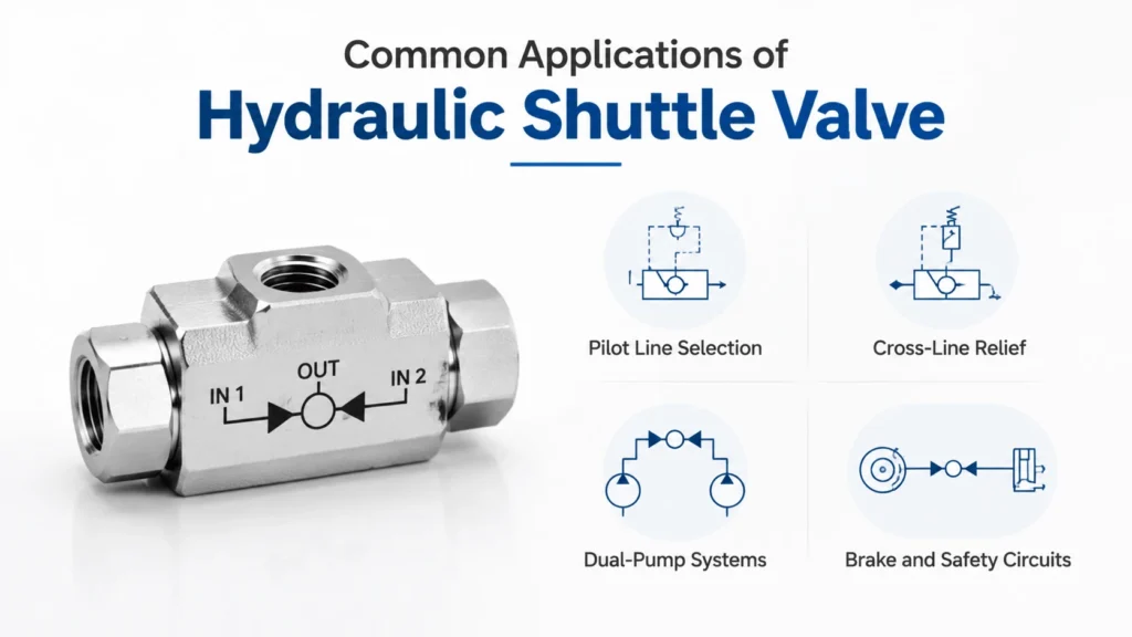
Pilot Line Selection
Many proportional and servo valves use remote pilot pressure for displacement control. A shuttle valve selects the higher of two pilot sources. If one pilot pump fails or depressurizes, the other takes over seamlessly.
Typical pilot shuttle valves run small flows of 1 to 5 L/min with cracking pressures around 0.3 bar. Cartridge-style bodies fit directly into the main valve manifold.
Cross-Line Relief
This is the number one use case for shuttle valves in industrial hydraulics. A cylinder or motor can generate overpressure at either end of its stroke. A cross-line relief circuit uses a shuttle valve to route the higher end pressure to a single relief valve.
Without the shuttle, you would need two relief valves. With it, one relief protects both ends. The shuttle sees the pressure at each rod end and sends the higher reading to the relief. This cuts component count, manifold drilling, and cost.
Dual-Pump Systems
Systems with main and standby pumps use a shuttle valve to select the active source. The main pump normally runs at a higher system pressure and keeps the shuttle shifted toward the standby side. If the main pump fails, pressure drops. The standby pump’s output shifts the shuttle and feeds the circuit.
Response time depends on the shuttle cracking pressure and the volume between the pump and valve. Keep the connecting lines short and the volume low for fast switchover.
Brake and Safety Circuits
Mobile equipment brake circuits often require dual-source pressure. A shuttle valve combines service brake pressure and parking brake pressure into a signal that confirms braking force exists. Both sources must show adequate pressure before the machine enables motion.
Similar logic applies to interlock circuits. Two independent pressure signals must both satisfy minimum thresholds. The shuttle reports the lower of the two for monitoring while passing the higher for functional use.
Application: Cross-Line Relief Circuit
Cross-line relief deserves detailed treatment because most industrial shuttle valves live here.
Consider a horizontal cylinder driving a load that can overcenter. At full extension, the piston side may overshoot and generate pressure above the system relief setting. At full retraction, the rod side faces the same risk if gravity pulls the load past the center.
A cross-line relief circuit places a shuttle valve across the A and B ports of the cylinder. The shuttle outlet connects to a relief valve set slightly above the system working pressure but well below the component burst rating.
When the A port spikes, the shuttle sends that pressure to the relief. When the B port spikes, the shuttle switches and sends B-side pressure to the same relief. One protection device covers both directions.
Size the relief for the worst-case overpressure flow. Calculate the flow from cylinder displacement divided by deceleration time. Add 20 percent margin. Set relief pressure 10 to 15 percent above normal working pressure, but never above the lowest-rated component in the circuit.
Application: Redundant Supply Circuits
Safety-critical machines sometimes require redundant hydraulic supplies. A flight control actuator might draw from two independent pumps. A steering system might have primary and backup power units.
A shuttle valve at the actuator inlet selects whichever pump delivers pressure. The active pump holds the shuttle against the standby side. If the active pump fails, pressure decay shifts the shuttle, and the standby pump takes the load.
Switchover time matters here. The actuator must not lose pressure long enough to drift or drop its load. Size the shuttle for low cracking pressure (0.2 to 0.3 bar) and minimize the volume between the shuttle and the actuator. Test switchover during commissioning and log the time.
Redundancy only works if the standby source stays ready. Monitor standby pressure continuously. A degraded standby pump that cannot reach system pressure will never shift the shuttle when needed.
Selection Guide
Start with the function you need. Do you want automatic selection between two pressure sources? That is a shuttle valve. Do you simply need to block reverse flow? That is a check valve.
Pick ball type for cost-sensitive, moderate-duty applications where minor leakage causes no problem. Pick a poppet type for tight-sealing, high-pressure, or low-leakage requirements. Expect to pay 30 to 50 percent more for poppet construction.
Match cracking pressure to your circuit dynamics. Low cracking (0.2 to 0.3 bar) gives a fast response for pilot and safety circuits. Higher cracking (0.7 to 1.0 bar) stabilizes main pressure selection where inlet pressures oscillate near each other.
Check the flow rating at your expected pressure drop. Catalog data usually lists flow at 3 or 5 bar delta P. Interpolate for your target drop. If your flow falls between catalog sizes, round up.
Verify port compatibility with your fittings. SAE J1926 straight-thread O-ring boss and ISO 6149 metric threads look alike but do not interchange. Check thread pitch and seat diameter before you order.
Installation and Plumbing
Mount the shuttle valve close to the point of use. Long lines between the source and the shuttle add volume that slows response time and traps compressible fluid. For pilot circuits, mount the shuttle directly in the manifold or subplate.
Orient the valve so that the outlet port points downward or horizontally. Vertical outlet-up mounting lets air collect in the shuttle chamber and cause erratic shifting. If vertical mounting is unavoidable, add a bleed screw at the highest point.
Plumb the shuttle so that the higher-pressure inlet corresponds to the normally-selected circuit. This keeps the shuttle stable during normal operation. The shuttle only shifts when the intended active source loses pressure.
Label both inlet ports at the manifold or hose assembly. Maintenance techs who work on the machine later will thank you. An unlabeled shuttle with identical-looking inlet ports invites crossed plumbing on reassembly.
Common Problems and Troubleshooting
| Symptom | Likely Cause | Action |
|---|---|---|
Continuous leakage from blocked port |
Worn seat, damaged seal |
Replace shuttle cartridge or reseal |
Erratic switching / dithering |
Cracking pressure too low, equal inlet pressures |
Increase cracking, check source pressures |
Shuttle sticks in one position |
Contamination, galled poppet, corroded ball |
Flush system, replace element |
High pressure drop across shuttle |
Undersized valve, high viscosity oil |
Step up size, check oil temperature |
Slow switchover on backup |
Excessive volume, high cracking pressure |
Reduce line length, lower cracking spec |
System overheats near shuttle |
Internal leakage, wrong viscosity |
Replace shuttle, verify ISO VG grade |
Contamination leads the list of shuttle valve failures. A particle caught between the ball and the seat or the poppet and bore prevents proper sealing. Once the seat scores, leakage becomes permanent. Pull oil samples quarterly and track ISO 4406 codes.
Dithering occurs when both inlet pressures fluctuate within the cracking pressure band. The shuttle shifts back and forth and wears both seats. Fix this by selecting a higher cracking pressure or adding accumulators to dampen pressure ripple at the sources.
Cold start problems usually trace to high oil viscosity rather than a faulty valve. Most mobile systems specify ISO VG 46 for normal operation. Verify that your heater or cold-weather startup procedure brings the oil within the viscosity window before you condemn the shuttle.
Maintenance
Inspect shuttle valves during planned maintenance events. Cycle the system and watch the gauge response at the outlet port. A slow or delayed pressure rise indicates a sticking element or partial blockage.
Replace ball and seat assemblies as a matched set. Never replace just the ball. The old seat has worn to match the old ball profile. A new ball on an old seat will not seal properly.
For poppet-type shuttles, replace the O-ring and backup ring at every major overhaul, even if they look intact. O-ring compression set happens gradually. A ring that held pressure at 25 degrees Celsius may leak at 80 degrees.
Log the pressure differential between inlets during normal operation. An increasing differential that was not present at commissioning signals developing restriction upstream of the lower-pressure source. Catch it early, and you save the pump or filter that is failing silently.
FAQ
What does a hydraulic shuttle valve do?
A hydraulic shuttle valve automatically selects the higher of two inlet pressures and routes it to a single outlet. It blocks the lower-pressure inlet. No external control needed. Engineers call this OR logic because the outlet receives pressure from inlet A OR inlet B, whichever is higher.
How does a hydraulic shuttle valve work?
Inside the valve body, a ball or poppet sits between two seats connected to the inlet ports. Pressure from the higher inlet pushes the sealing element against the opposite seat. This opens a path from the higher-pressure inlet to the outlet while sealing off the lower-pressure side. The element shifts instantly when the pressure balance reverses.
What is the difference between a shuttle valve and a check valve?
A check valve permits flow in one direction and blocks reverse flow. It has two ports and one sealing element. A shuttle valve has three ports and selects between two inlets. Think of a shuttle valve as two check valves sharing one outlet and one moving seal. Use a check valve to hold a load. Use a shuttle valve to choose between two sources.
Where are shuttle valves used in hydraulic systems?
Common applications include cross-line relief circuits (one relief valve protecting both sides of a cylinder), dual-pump redundant supply selection, pilot line priority selection, and brake/safety interlock circuits. Cross-line relief accounts for the majority of industrial shuttle valve installations.
Why use a shuttle valve instead of two check valves?
A shuttle valve integrates both check functions in one body with one moving seal. Two separate check valves give you four seal points, twice the potential leakage, more connections to plumb, and higher cost. The shuttle valve does the same job with half the parts and half the leakage paths.
What causes a hydraulic shuttle valve to leak?
Worn ball seats, damaged poppet O-rings, scored bore surfaces, and contamination particles lodged in the seal zone all cause leakage. Contamination is the root cause in most cases. Maintain ISO 4406 18/16/13 cleanliness or better for poppet shuttles and replace sealing elements at scheduled intervals.
How do I size a hydraulic shuttle valve?
Match the flow rating to your peak flow with a pressure drop under 2 bar. Select cracking pressure based on circuit behavior: 0.2 to 0.3 bar for fast-response pilot and safety circuits, 0.7 to 1.0 bar for stable main pressure selection. Choose ball type for moderate duty and poppet type for tight sealing or pressures above 350 bar.
Conclusion
A hydraulic shuttle valve solves one problem cleanly: pass the higher of two pressures to one outlet and ignore the lower one. No electronics. No operator. Just pressure mechanics.
Pick the right design for your application. Ball-type shuttles handle dirty oil and tight budgets. Poppet-type shuttles seal tighter and handle higher pressure at the cost of contamination sensitivity. Most industrial users find the poppet type worth the premium for cross-line relief and redundant supply circuits.
Size for flow and cracking pressure. Install close to the point of use with the outlet down or horizontal. Label the inlets. Keep the oil clean. Log the differential pressure during routine checks. A properly specified and maintained shuttle valve lasts years between services.