
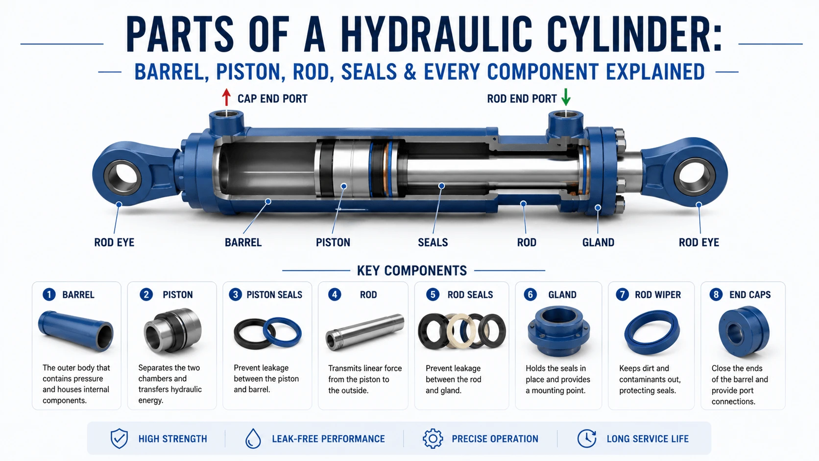
Parts of a hydraulic cylinder have eight core assemblies:
| Assembly | Function | Typical Quantity |
|---|---|---|
Cylinder barrel |
Pressure vessel containing fluid and piston |
1 |
Piston |
Divides pressure chambers, transmits force |
1 |
Piston rod |
Carries output force to external load |
1 |
Gland (rod end head) |
Houses rod seals and guides the rod |
1 |
Blind end cap |
Seals rear of barrel, provides rear mount |
1 |
Seals |
Prevent fluid leakage (internal and external) |
5–12 depending on design |
Wear bands / bearings |
Prevent metal-to-metal contact between moving parts |
2–6 |
Ports and fittings |
Connect cylinder to hydraulic lines |
2–4 |
Single-acting telescopic cylinders add stages. Welded-body constructions merge the barrel and end caps into one piece. But the fundamental parts list above applies to 80% of industrial and mobile equipment cylinders in service today.
Cylinder Barrel
The barrel is the pressure vessel. It contains hydraulic fluid on both sides of the piston and withstands the full system pressure. Get this wrong, and nothing else matters.
Material and Construction
Most barrels are seamless cold-drawn steel tubes to SAE J524 or DIN 2391. Carbon steel grades like ST52 (E355) handle pressures up to 250 bar. For 350+ bar systems, manufacturers use higher-strength alloy steel or increase the wall thickness. Aluminum barrels appear in low-pressure aerospace and racing applications but rarely in industrial settings because aluminum creeps under sustained load.
Wall thickness follows the thin-pressure-vessel formula (Barlow’s equation) plus a safety margin. A 100 mm bore cylinder rated for 210 bar typically has 5–7 mm wall thickness depending on steel grade. At 350 bar, expect 8–10 mm on the same bore.
Internal Surface Finish
The inside of the barrel gets honed to a mirror-like finish. Target surface roughness: Ra 0.2–0.4 µm (8–16 µin). This is not cosmetic. The piston seals ride directly against the honed surface. Rougher finishes chew through seal lips in hundreds of hours. Smoother finishes extend seal life dramatically but cost more to produce.
Honing also creates a shallow cross-hatch pattern that retains a microfilm of oil between the seal and barrel wall. That film prevents dry running during the first few millimeters of each stroke. A barrel that looks shiny but lacks proper cross-hatch will wear seals faster than one with the right texture.
Piston
The piston sits inside the barrel and splits it into two pressure chambers: the blind end (cap end) and the rod end. Hydraulic pressure pushes against the piston face. Force transfers through the piston to the rod.
Piston Design Types
Most industrial pistons are solid steel discs machined from bar stock or forgings. Two designs dominate:
- Integral pistons machined as one piece with seal grooves and bearing lands. Simple, rigid, used in medium-duty applications.
- Assembly pistons consisting of a separate piston body, locknut, and washer are clamped onto the rod thread. Used in heavy-duty and high-pressure cylinders where the piston must be removable without rod extraction.
The assembly type costs more but saves hours during rebuilds. You can swap seals and wear bands without pulling the entire rod out of the barrel.
Seal Grooves and Tolerance
Piston seal grooves follow ISO 5597 or DIN ISO 7425 profiles for standard seals. Groove dimensions matter more than most people realize. A groove 0.15 mm too wide lets the seal roll into the gap under pressure. Too narrow and the seal compresses unevenly, creating leakage paths.
If you are machining a custom piston, get your seal supplier’s groove drawing before cutting metal. Parker, Hallite, and Trelleborg publish free CAD files for every profile they sell. Use them.
Piston Rod
The rod extends from the piston through the gland to the outside. It carries the full output force in tension during retraction and in compression during extension, where buckling becomes a risk. Side loads also land on the rod whenever the cylinder mount is misaligned or the load swings.
Material and Surface Treatment
Rods start as medium-carbon steel bars (C45 / 1045 or equivalent). The critical feature is the hard chrome plating on the working surface. Standard chrome thickness: 0.02–0.05 mm (0.0008–0.002″). Hardness typically 900–1100 HV.
Chrome does two things. First, it provides a low-friction surface for the rod seals to ride against. Second, it resists corrosion and abrasion from environmental exposure. The rod is the only cylinder part that sticks out into dust, rain, mud, and weld spatter.
High-duty applications sometimes use ceramic coatings (chrome oxide plasma spray) or nickel-chrome duplex layers instead of plain hard chrome. These last longer in abrasive mining environments but cost 2–3x more.
Buckling Considerations
Long strokes create column buckling risk during extension. Euler’s formula applies here, and every cylinder manufacturer publishes buckling charts for each rod diameter and mounting configuration. As a rule of thumb, if the free length of the exposed rod exceeds 15–20 times its diameter, verify buckling capacity before putting the cylinder in service. A 50 mm rod with 1000 mm of exposed length is fine. That same rod at 1500 mm may buckle under half its rated load.
Gland (Rod End Head)
The gland bolts or threads onto the front of the barrel. It does three things: guides the rod, houses the rod sealing package, and usually serves as the rod-end mounting point.
Construction Methods
Two approaches dominate:
- Threaded glands screw into a tapped barrel end. A locknut or staking wire prevents loosening. Field service can remove them with strap wrenches. Common on mobile equipment cylinders up to 150 mm bore.
- Bolted glands use a flange with cap screws around the rod opening. Stronger and easier to seal at high pressure (280+ bar), but require more circumferential space. Standard on large-bore industrial presses.
Some welded-body cylinders eliminate the gland entirely by welding the rod-end cap directly to the barrel. Rebuilding those requires cutting the weld, which means the cylinder is effectively disposable in many maintenance contexts.
Bearing Area Inside the Gland
Behind the rod seals, the gland contains a guide bearing (often called the rod bushing). Bronze-filled PTFE or hardened steel bushings are common. This bearing takes the side load and keeps the rod centered as it reciprocates. When the rod bushing wears out, the rod tilts slightly, and the rod seal life drops by 50% or more. Check rod bushing clearance during every rebuild.
Blind End Cap (Rear Head)
The blind end cap closes the back of the cylinder barrel. On most designs, it also holds the blind-end port fitting and provides the rear mounting feature (clevis ear, trunnion pad, or flange face).
Welded cylinders fuse the blind end cap to the barrel with a full-penetration butt weld. Tie-rod cylinders clamp the end cap between the tie-rod nuts and the barrel flange. Mill-type heavy-duty cylinders often thread the cap into the barrel, similar to the gland, or bolt it with a ring of high-strength socket head capscrews.
The blind end sees the highest pressure force in the cylinder. The full-bore area acts on it with no rod area subtracted. Cap retention design reflects this. A 200 mm bore cylinder at 350 bar puts roughly 1,100 kN of thrust against the blind end cap. Hold that cap down properly, or it will move.
Piston Seals
Piston seals prevent fluid from leaking between the two pressure chambers as the piston moves. Internal leakage (bypass) reduces effective force and creates heat. In severe cases the cylinder drifts under load.
Seal Types by Application
| Seal Type | Max Pressure | Speed Range | Best For |
|---|---|---|---|
U-cup (polyurethane) |
250–350 bar |
Medium speed (<0.5 m/s) |
General industrial |
Stepped seal (PTFE + elastomer) |
350–500 bar |
High speed (>0.5 m/s) |
Mobile equipment, long stroke |
Glyd-ring (O-ring + PTFE slider) |
210–315 bar |
Low-medium speed |
Compact cylinders, light duty |
Pneumatic-style lip seal |
<16 bar |
Very high speed |
Low-pressure applications |
Polyurethane U-cups dominate the general industry because they balance cost, pressure capability, and friction. PTFE-based stepped seals run cooler at high speed and last longer in continuous-cycle applications, but cost 3–5x more.
Double-acting cylinders have piston seals on both faces of the piston. Single-acting (spring-return or load-return) cylinders only need a seal on the pressurized side.
Rod Seals
The rod sealing package is where most external leaks originate. It sits in the gland and seals around the moving rod. Unlike piston seals, rod seals operate with system pressure pushing outward. The pressure tries to extrude the seal into the gap between the rod and the gland. This makes the design harder.
Typical Rod Seal Stack (high-pressure industrial cylinder)
From outside to inside:
- Wiper seal (scraper) — removes dirt, mud, and moisture from the rod surface before it enters the gland. Usually nitrile or polyurethane. A stiff wiper lip that rides tight against the rod.
- Rod seal (primary) — the main pressure seal. U-cup, stepped seal, or buffer-rod-seal combo, depending on pressure and duty cycle.
- Buffer seal — sits between the rod seal and the bearing. Its job is to absorb pressure spikes in the gap behind the rod seal and protect the primary seal from extrusion damage. Often, a simple O-ring or D-ring.
- Backup ring(s) — anti-extrusion rings (usually PTFE or filled nylon) that mechanically block the gap so the seal cannot get squeezed into it. One backup ring handles 210 bar. Two in series handle 350 bar+. Essential above 250 bar.
Not all cylinders use all four elements. Light-duty cylinders might combine the wiper and rod seal into one dual-lip component. But any cylinder running above 200 bar in dirty environment should have the full stack.
Wear Bands and Bearing Bands
Wear bands (also called wear rings, guide rings, or bearing bands) stop metal-to-metal contact. They keep the piston off the barrel wall and the rod off the gland bearing. Without them, steel-on-steel friction scores the barrel and wears through the rod coating.
Material Options
| Material | Max Pressure | Temp Limit | Cost | Typical Use |
|---|---|---|---|---|
Phenolic resin (fabric-reinforced) |
350 bar |
120°C |
Low |
General industrial |
PTFE-bronze filled |
400+ bar |
200°C |
Medium-High |
High-pressure, high-temp |
Fiberglass-reinforced PTFE |
300 bar |
180°C |
Medium |
Chemical resistance needed |
Hardened steel (split bushing) |
700+ bar |
300°C |
High |
Extreme-pressure presses |
henolic wear bands handle 90% of industrial applications. They are cheap, easy to cut to size, and last 5,000–10,000 hours in clean systems at 210 bar. Upgrade to PTFE-bronze if you see temperatures above 100°C or pressures over 280 bar consistently.
Wear band width matters too. Narrow bands (8–10 mm) concentrate the side load. Wide bands (20–30 mm) distribute it. Heavy side-loaded cylinders (dump hoists, crane outriggers) should use wide wear bands on the piston.
Ports and Fittings
Ports connect the cylinder to the rest of the hydraulic circuit. Minimum configuration: one port on the blind end, one on the rod end. Additional ports appear for drain lines, cushion adjustment, or position transducers.
Port Sizing Rules
Port diameter determines maximum flow velocity into and out of the cylinder chamber. Undersized ports choke flow, causing pressure drop and slow cylinder response. Oversized ports add cost and weak points in the pressure envelope.
Practical rule: make the port area at least 10% of the piston annular area for the rod end, or 8% of the full bore area for the blind end. A 100 mm bore cylinder moving at 0.3 m/s needs roughly 24 L/min flow per side. A G 1/2 BSPP port handles that easily. A 3/8″ port would be marginal.
Thread Standards
Match the thread standard to your existing fittings. BSPP (parallel BSP) dominates European and Asian-built equipment. NPT appears on North American machinery. Metric threads show up on newer ISO-standard cylinders and German-made components. Mixing them forces adapters and creates leak points.
Cushions and Stop Tubes
These two features protect the cylinder from end-of-stroke impact damage.
Cushion Plungers
A cushion plunger is a tapered needle or stepped boss on the piston (or end cap). It gradually blocks fluid exit near the end of the stroke. The trapped fluid compresses and slows the piston before metal contacts metal.
Two types exist:
- Fixed cushions: built into the piston or cap geometry. Non-adjustable. Simple and reliable, but inflexible if cycle times change.
- Adjustable cushions: needle valve built into the end cap port. You turn a screw to change the orifice size and tune the deceleration rate. Preferred on variable-speed equipment.
Cushions typically engage during the final 15–25 mm of stroke. If your cylinder bangs at the end of travel and lacks cushions, add an external shock absorber or upgrade to a cushioned cylinder. Let an end cap fracture once, and you will not forget it.
Stop Tubes
A stop tube is a spacer sleeve between the piston and the gland. It shortens the piston’s available stroke to keep the rod fully supported within the gland bearing even at full extension. Short rods with long strokes are vulnerable to side-load bending at full extension. The stop tube sacrifices some stroke to buy bending safety.
Industry guideline: install a stop tube if the stroke exceeds 10 times the rod diameter. Minimum stop tube length = stroke / 3 for moderate side loading. More for heavy side loads.
Common Failure Modes by Component
Understanding which part fails first helps with diagnosis and preventive action.
| Component | Typical Failure Mode | Root Cause | Mean Time Between Failures* |
|---|---|---|---|
Rod wiper |
Cracking, hardening, loss of lip tension |
UV exposure, ozone, age |
2,000–4,000 hours |
Rod seal |
Lip wear, extrusion, spiral failure |
Contamination, high temp, pressure spike |
3,000–8,000 hours |
Buffer seal |
Crushing, fragmentation |
System pressure spikes >rated |
5,000–12,000 hours |
Wear band |
Cracking, delamination, excessive wear |
Side loading, contamination |
6,000–15,000 hours |
Piston seal |
Bypass, lip extrusion, chemical swell |
Wrong seal material for fluid/temp |
8,000–15,000 hours |
Rod chrome |
Pitting, scoring, wear-through |
Corrosive atmosphere, lack of wiper protection |
10,000–20,000 hours |
Barrel ID |
Scoring, taper, ovalization |
Contamination ingress, seal debris embedded |
15,000–30,000 hours |
Gland bearing |
Egg-shape, seizure |
Misalignment, insufficient lubrication |
15,000–25,000 hours |
*Ranges assume ISO 18/16/13 oil cleanliness, operating temperature below 70°C, and pressure within cylinder rating. Contaminated oil cuts all these figures by 60–80%.
The pattern tells a story: seals fail before metal parts, and external seals fail before internal ones. Your rod wiper is the cheapest component in the cylinder and the one that protects everything downstream. Replace it proactively.
Selection and Procurement Checklist
When ordering cylinder components or specifying a new unit, document these parameters:
Barrel and Caps:
- Bore diameter (nominal per ISO 3320)
- Wall thickness or pressure rating
- Barrel material (carbon steel grade)
- Mounting style (clevis, trunnion, flange, foot, tang)
- Mounting pin diameter and spacing
Piston and Rod:
- Rod diameter and area ratio (extend: retract force ratio)
- Stroke length (mechanical, not just usable)
- Rod surface treatment (hard chrome, ceramic, etc.)
- Piston type (integral vs. assembly)
Sealing System:
- Operating pressure (max continuous and peak)
- Fluid type and temperature range
- Seal material compatibility (nitrile, Viton, polyurethane, PTFE)
- Number and position of seals (full stack vs. simplified)
- ISO 5597 groove compliance or custom dimensions
Ports:
- Port size and thread type (BSPP, NPT, metric)
- Number of ports (including drains, cushions)
Duty Cycle:
- Cycles per hour/day
- Side load magnitude and direction
- Environmental exposure (temperature, humidity, abrasives)
Send this list to your supplier. Missing one item causes delays or wrong parts.
FAQ
What are the main parts of a hydraulic cylinder?
Eight core assemblies make up a standard double-acting hydraulic cylinder: the barrel (pressure vessel), piston (pressure divider), piston rod (force output), gland (rod seal housing and guide), blind end cap (rear closure), seals (leakage prevention), wear bands (prevent metal contact), and ports (fluid connections).
Each assembly contains sub-components. The gland alone holds a wiper, a rod seal, a buffer seal, backup rings, and a rod bushing. Total individual parts in a typical industrial cylinder range from 20 to 40, depending on pressure rating and mounting complexity.
What does the gland do on a hydraulic cylinder?
The gland (also called the rod end head or front head) does three things. It guides the piston rod to keep it aligned with the barrel axis. It houses the entire rod sealing package: wiper, rod seal, buffer seal, and backup rings. And it usually provides the rod-end mounting interface, whether that is a clevis eye, trunnion pad, or flange face.
The gland takes significant radial load from rod misalignment and side forces. That is why the internal rod bushing wears out and needs checking during every cylinder rebuild.
How many seals does a typical hydraulic cylinder have?
A medium-pressure (210 bar) industrial double-acting cylinder typically runs 8–10 seals. That includes two piston seals (one per face), one rod wiper, one primary rod seal, one buffer seal, two rod-side backup rings, and one or two static O-rings for end-cap sealing.
High-pressure (350+ bar) or severe-duty cylinders add extra backup rings, secondary rod seals, and sometimes a dedicated pressure-boost ring. Single-acting cylinders need fewer seals since only one pressure chamber requires dynamic sealing.
What is a wear band, and why do cylinders need them?
Wear bands (also called guide rings or bearing bands) sit in grooves on the piston or rod. They maintain a small, controlled clearance between moving metal surfaces. The piston cannot contact the barrel wall. The rod cannot contact the gland bearing.
Without wear bands, metal-on-metal friction quickly scores the honed barrel ID and damages the rod chrome plating. Wear bands are sacrificial items. You replace them during rebuilds so they protect the far more expensive components. Material is typically fabric-reinforced phenolic resin for general use, or PTFE-bronze composite for high-pressure, high-temperature applications.
What is the difference between a piston seal and a rod seal?
Piston seals seal between the piston outer diameter and the barrel inner diameter. They stop the internal bypass, which means fluid leaks from the high-pressure side to the low-pressure side around the piston.
Rod seals seal between the piston rod outer diameter and the gland inner diameter. They stop the external leakage of system fluid out of the cylinder. Rod seals face a harder job because system pressure pushes outward against the seal, trying to extrude it into the rod-gland gap. That is why rod seal stacks include backup rings and buffer seals that piston seals often omit.
Can you replace individual cylinder parts, or must you buy a whole new cylinder?
Nearly all cylinder parts are replaceable individually. Seals and wear bands are consumables replaced during routine rebuilds, every 3,000 to 8,000 operating hours, depending on duty cycle. You can re-chrome or replace worn rods. Barrels can take oversize honing with matching oversized pistons and seals, but this approach has limits: typically, one oversize step of 0.5–1.0 mm before you must replace the barrel outright.
Glands, pistons, and end caps can be sourced or machined as spare parts for most standard cylinder series. The exception is welded-body construction. Those designs fuse the barrel and end caps together, which limits field repair to seal replacement via rod removal only.
Conclusion
Every cylinder part exists for a reason. The barrel holds pressure. The piston divides it. The rod delivers force. The gland guides and seals. The seals contain fluid. The wear bands prevent contact. None of these components works in isolation. A worn wiper lets dirt reach the rod seal. A damaged rod seal leaks, dropping pressure, and letting air in. Air causes cavitation and heat. Heat degrades the piston seals. Piston seal bypass reduces force. The operator pushes harder. Pressure spikes crush the buffer seal. And suddenly you are rebuilding the whole thing.
Know the parts. Inspect them systematically. Replace seals before they fail completely. Keep oil clean. That routine extends cylinder life from months to years. It all starts with understanding what every component inside that tube actually does.