
Introduction
What is a Track Motor
How a Track Motor Works
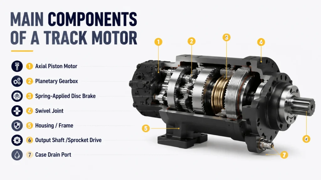
Main Components of a Track Motor
| Component | Function | Typical Specification |
|---|---|---|
Axial Piston Motor |
Converts hydraulic flow to mechanical rotation |
Fixed or variable displacement; 25–160 cc/rev |
Planetary Gearbox |
Multiplies torque, reduces output speed |
2–4 stages; ratio 15:1 to 60:1 |
Spring-Applied Disc Brake |
Holds machine stationary when de-energized |
Release pressure 15–25 bar; static holding torque rated |
Swivel Joint |
Delivers pressurized oil to rotating motor group |
Dual-port for bidirectional operation |
Housing / Frame |
Mounts unit to chassis, encloses internals |
Cast iron or ductile iron; SAE J1926 ports |
Output Shaft / Sprocket Drive |
Transfers torque to machine track sprocket |
Splined or tapered connection; sealed against debris |
Case Drain Port |
Returns internal leakage oil to tank |
Must stay below 3–5 bar back-pressure |
Each part is field-replaceable on most models above 5-ton class. Smaller mini-excavator motors usually come as sealed units. On those, only external seals can be serviced.
Track Motor vs Travel Motor vs Final Drive
These three terms show up interchangeably in parts catalogs. Here is what each actually points to:
- Track motor: Emphasizes the application—propelling a tracked undercarriage.
- Travel motor: Focuses on the hydraulic motor element inside the assembly.
- Final drive: Describes the position in the power train—the last reduction stage before the sprocket.
All three refer to the same bolt-on unit. The name you see depends on the supplier. Hydraulic suppliers list them as “travel motor.” OEM parts desks call them “final drive.” General industrial distributors use “track motor.” No functional difference exists between the three terms.
One distinction worth noting: some manufacturers sell the motor group (piston motor plus valve plate) separately from the gearbox assembly. If someone says “travel motor” they may mean just the motor half. Always confirm whether the price includes the planetary section.
Types of Track Motors
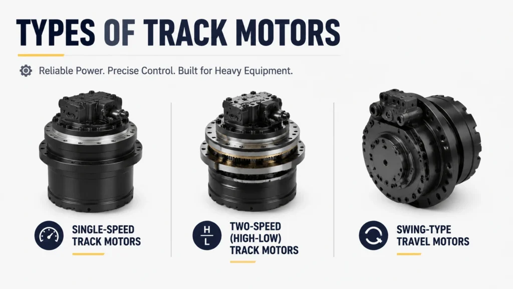
Single-Speed Track Motors
Two-Speed (High-Low) Track Motors
Swing-Type Travel Motors
Key Specifications
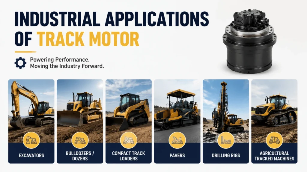
Industrial Applications of Track Motor
| Application | Machine Examples | Typical Pressure Range | Notes |
|---|---|---|---|
Excavators |
Cat 320, Komatsu PC200, Hitachi ZX200 |
350–400 bar |
Most common application; two-speed units common on >20t class |
Bulldozers / Dozers |
Caterpillar D6, Komatsu D65 |
380–420 bar |
Higher continuous load; larger displacement motors |
Compact Track Loaders |
Bobcat T66, Case TV380 |
300–350 bar |
Sealed-unit motors; lower pressure rating |
Pavers |
Vögele Super 1800, Caterpillar AP1055F |
250–320 bar |
Lower speed, precise creep control needed |
Drilling Rigs |
Soil nail drills, foundation drilling rigs |
350–400 bar |
High torque demand; often custom ratios |
Agricultural Tracked Machines |
Challenger MT800 series, Yanmar tracked tractors |
280–340 bar |
Long duty cycles; dust-heavy environments |
The excavator segment alone accounts for roughly 65% of global track motor volume. Aftermarket demand runs about 2–3 times OEM volume as machines age out of warranty coverage.
Advantages
Several design features make track motors well-suited to mobile tracked equipment:
High Power Density. A 50 kg motor assembly can produce 15,000+ Nm of torque at the sprocket. Electric drives with equivalent output would weigh substantially more and require larger mounting space.
Integrated Brake. The spring-applied disc brake provides fail-safe holding without separate components. The machine will not roll away even if the hydraulic hose bursts.
Bidirectional Operation. Instantly reversing the oil flow direction reverses the output shaft through the same planetary train. No extra gears or clutches required.
Sealed Construction. The housing protects internal gears and bearings from mud, grit, and water ingress better than exposed drivetrain arrangements.
Modular Repair. You can address most failures by replacing the motor group, the gearbox, or the brake pack individually. There is no need to scrap the entire unit.
Disadvantages / Limitations
Track motors also have constraints worth understanding:
Cost. A genuine OEM final drive for a 20-ton excavator runs 3,000–7,000 USD, depending on brand. Aftermarket alternatives start around $1,200, but quality varies widely.
Heat Buildup. Continuous high-load travel (long uphill hauls, ripping operations) pushes oil temperature past 90°C quickly. Many machines lack dedicated travel motor cooling circuits, so the heat dumps into the main reservoir.
Sensitivity to Contamination. Particulate above ISO 4406 18/16/13 accelerates piston and valve plate wear. A single contamination event can cut expected life in half.
Case Drain Back-Pressure Risk. Plugged or undersized case drain lines raise internal pressure, blowing shaft seals outward and overloading bearings. This is the number-one preventable failure cause in field service records.
Weight. A pair of large travel motors adds 150–300 kg to the undercarriage. On smaller machines, this represents a meaningful percentage of total operating weight.
Common Failure Modes
Excavator repair shops see the same failure patterns over and over:
Outer Shaft Seal Leakage. Oil drips from the sprocket-end seal. The cause is almost always elevated case drain pressure (>5 bar), not a defective seal. The root cause is usually a restricted drain line, a collapsed hose, or the drain line routed into a pressurized return line by mistake.
Gearbox Bearing Spalling. Planet gear or carrier bearings develop surface pits from shock loading. Symptoms include a growling noise during travel and metallic particles in the drained oil. Once spalling starts, progressive failure occurs within 100–200 operating hours.
Brake Drag or Failure to Release. The disc brake stays partially engaged during travel. You feel resistance, see higher travel pressure readings, and notice the motor housing running hot. Causes: insufficient pilot pressure to the brake release port (below 15 bar), corroded brake piston, or warped discs from overheating.
Motor Group Internal Leakage. A worn valve plate or scored piston shoes allow high-pressure oil to bypass to the case drain. The result is slow travel speed on one side and elevated case drain flow. Measure the case drain flow with a flow meter to get a clear diagnosis. Anything above 3–4 L/min on a healthy-sized motor warrants teardown.
Swivel Joint Scoring. The rotating seal surface between the housing and the motor group develops grooves from contaminated oil or dry startup. Cross-leakage between the A and B ports reduces effective flow to the motor.
Troubleshooting Guide
Use this diagnostic sequence when a track motor acts up. Each step narrows the problem:
- Check the case drain back-pressure first. Install a gauge on the case drain port while the machine travels under load. Anything above 3–5 bar indicates a plumbing problem, not a motor problem. Fix the drain line before touching the motor.
- Compare left vs. right travel pressure. Use the test ports on the main control valve. A difference greater than 15–20 bar between sides suggests the weaker motor has internal leakage or a stuck brake. Equal high pressure on both sides points to an undercarriage issue (track tension, seized carrier rollers).
- Measure the case drain flow rate. Connect a graduated container or flow meter to the case drain line. Record flow at neutral, low speed, and high speed. A jump from 0.5 L/min at neutral to 4+ L/min under load confirms valve plate or piston wear.
- Inspect brake release pressure. Tee a gauge into the brake release line. Pressure should reach 20–35 bar during normal travel. Below 15–18 bar means the brake is dragging.
- Check for external leaks. Trace any visible oil to its source. Sprocket-end leaks = case drain issue. Housing seam leaks = internal pressure buildup or porous casting (rare). Port-end leaks = failed O-ring or damaged seat.
- Listen for noise patterns. A steady whine that changes pitch with speed points to motor group wear. An intermittent grinding or clicking sound during direction change suggests loose planet gears or damaged gear teeth.
Document your readings at each step. The combination of pressure values, flow numbers, and noise signatures usually pinpoints the failed sub-assembly before disassembly begins.
Selection Guide
Sizing a track motor replacement or new-application unit follows four steps:
Step 1: Determine Required Sprocket Torque
Calculate the tractive force needed at the track ground contact point:
Traction Force (N) = Machine Weight (N) × Grade Factor × Rolling Resistance Coefficient
For a 20-ton (196,000 N) machine climbing a 30% grade with rubber tracks on firm soil:
- Grade factor = sin(arctan(0.30)) ≈ 0.287
- Rolling resistance ≈ 0.03–0.05 for rubber tracks
- Required traction ≈ 196,000 × (0.287 + 0.04) ≈ 64,500 N
Convert to sprocket torque using the sprocket radius (typically 0.28–0.38 m for 20-ton class):
Required Torque (Nm) = Traction Force (N) × Sprocket Radius (m)≈ 64,500 × 0.33 ≈ 21,285 Nm
Apply a 20% safety margin for shock loads: target ≥ 25,500 Nm.
Step 2: Select Motor Displacement
Use the motor’s torque constant (Nm/bar) from the catalog:
Motor Torque = Displacement (cc/rev) × Pressure (bar) × ηm / (2π × 100)
Where ηm (mechanical efficiency) = 0.90–0.95 for a good-quality piston motor.
For a target output torque of 25,500 Nm with a 45:1 gear ratio and 370 bar working pressure:
- Required motor shaft torque = 25,500 / 45 ≈ 567 Nm
- Rearranging: Displacement = (567 × 2π × 100) / (370 × 0.92) ≈ 105 cc/round
Select a 107 cc/rev or 110 cc/rev motor model.
Step 3: Verify Speed Capability
Confirm the motor reaches the desired travel speed at the available pump flow:
Output RPM = (Flow L/min × 1000 × ηv) / (Displacement cc/rev × Gear Ratio)
With 200 L/min available flow, 110 cc/rev displacement, 45:1 ratio, and 0.94 volumetric efficiency:
Output RPM = (200 × 1000 × 0.94) / (110 × 45) ≈ 37.9 RPM
Check if this matches the machine’s designed travel speed. If too slow, consider a two-speed motor or increase pump flow capacity.
Step 4: Confirm Case Drain Capacity
Ensure the return line and case drain circuit handle the expected leakage flow:
Expected Case Drain (L/min) = Pump Flow × (1 − ηv)= 200 × 0.06 ≈ 12 L/min total (both motors combined)
Size the case drain hose for at least 1.5× expected flow with minimal restriction. Never tee case drain into a line carrying more than 2 bar back-pressure.
If these calculations seem involved, most reputable suppliers offer sizing spreadsheets. Provide machine weight, sprocket radius, max travel speed, and available pump flow—they will recommend matching models.
Maintenance Tips
Good preventive maintenance adds thousands of hours to a track motor’s life. Focus on these items:
Oil Cleanness. Maintain hydraulic fluid at ISO 4406 18/16/13 or better. Every 50-hour visual check of the tank breather cap and filter condition indicator. Change filters on schedule—never extend intervals because “the fluid looks clean.”
Case Drain Line Inspection. Check for kinks, flat spots, or crushed sections every 500 hours. Replace hoses every 2,000 hours regardless of appearance. Internal reinforcement breakdown restricts flow without showing external damage.
Break-In Procedure. New or rebuilt motors need a run-in period. Start with 30 minutes of idle travel, then 2 hours of light-load travel. Gradually increase load over the next 8 operating hours. Skipping the break-in glazes the valve plate surface and cuts efficiency permanently.
Torque Check on Mounting Bolts. Loose mounting bolts allow micro-movement between the motor housing and chassis frame. This fretting damages the machined mounting face and eventually misaligns the output shaft. Re-torque to OEM specification at 500-hour intervals.
Temperature Monitoring. Use an infrared thermometer to spot-check motor housing temperature after sustained travel under load. Readings exceeding 95°C indicate either excessive load, low system flow, or developing internal friction. Investigate immediately rather than waiting for failure.
Bearing Play Check. Grab the output sprocket and rock it radially and axially during track maintenance. Any perceptible play beyond the specified lash (usually < 0.05 mm radial) means the output bearing is approaching end-of-life. Plan replacement before catastrophic seizure.