What is a Proportional Valve? Types, Working Principle & Selection

What is a Proportional Valve- Types, Working Principle & Selection

Table of Contents

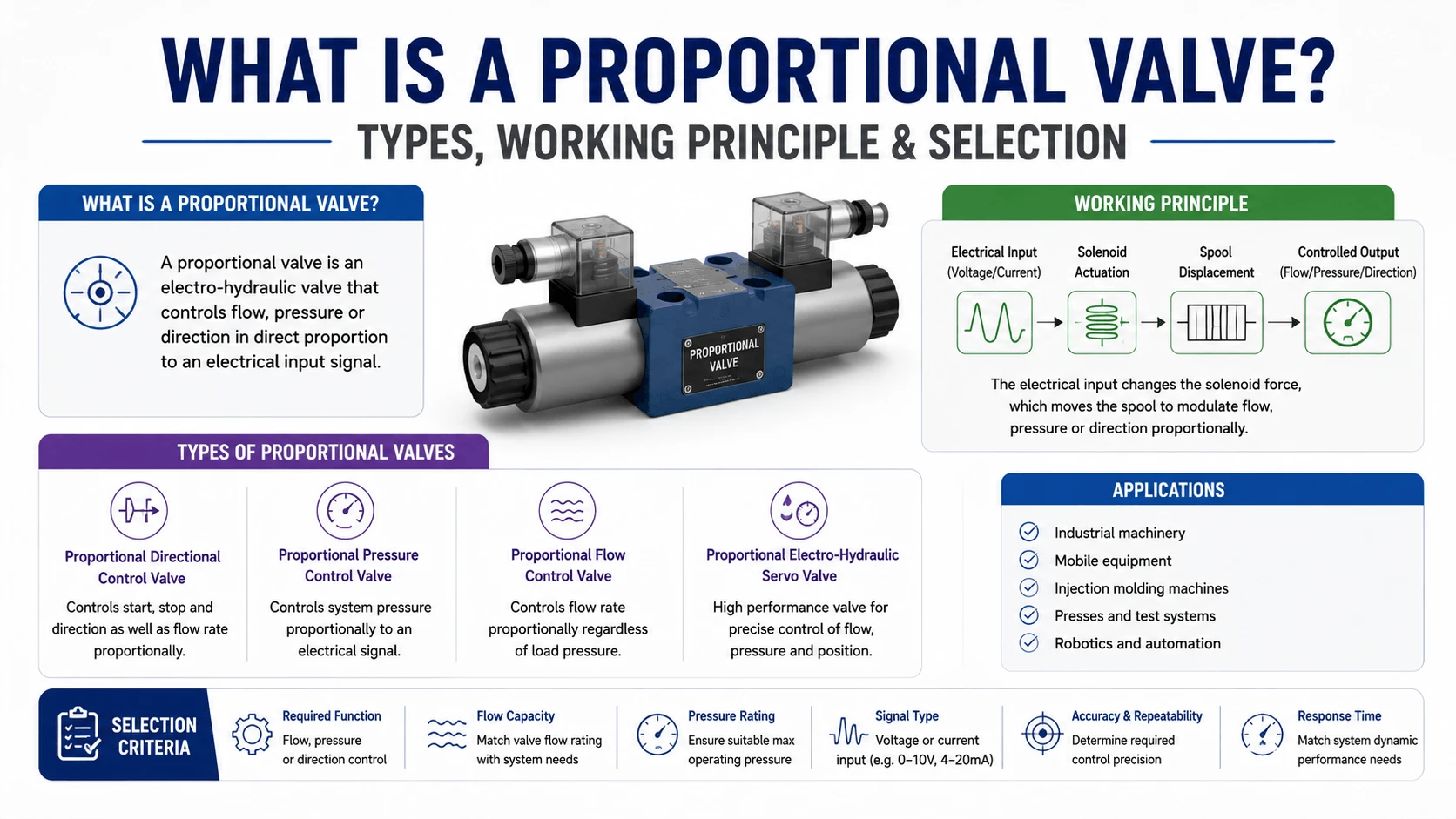
A proportional valve is an electro-hydraulic valve where the position of the control element (spool, poppet, or throttle) changes continuously in proportion to an electrical input signal. Unlike standard on/off solenoid valves that simply switch between two fixed positions, it can move and hold at any point between those limits.

This continuous control makes it possible to achieve stepless regulation of flow, pressure, and actuator speed, as well as smooth acceleration and deceleration. In many applications, a single proportional directional valve can replace a traditional directional valve, a flow control valve, and the connecting plumbing, all managed electronically through a PLC.

The movement is generated by a proportional solenoid, which produces force based on input current rather than binary switching. A driver amplifier converts control signals such as 0–10V or 4–20mA into precise coil current. In closed-loop versions, a position sensor feeds the actual spool position back to the controller, allowing it to compensate for flow forces, hysteresis, and temperature drift.

Positioned between standard on/off valves and high-end servo valves, proportional valves offer a strong balance of performance, cost efficiency, and tolerance to contaminated hydraulic oil.

How a Proportional Valve Works

The proportional solenoid and force balance

The proportional solenoid is the heart of the valve, and it behaves differently from a switching solenoid. A switching solenoid is designed to pull in and hold; its force drops sharply once the armature seats. 
 
A proportional solenoid is designed with a deliberately shaped magnetic circuit so that the force stays roughly constant across a useful working stroke. That means coil current maps to force, and force maps to spool position.
 
Inside the valve, the spool is held between two opposing springs and one or two solenoids. When you command 50% flow, the driver pushes current through solenoid A. 
 
The solenoid pushes the spool against the return spring until the spring force balances the solenoid force. The spool lands at the position that gives roughly half the notch opening, and therefore roughly half the rated flow at the rated pressure drop.
 
The word “roughly” is doing a lot of work there. In an open-loop valve, the spool position depends entirely on that force balance, and the balance is disturbed by three things: flow forces (the oil pushing back on the spool, which rise with pressure drop and flow), friction, and the solenoid’s own hysteresis (magnetic remanence means the current-to-force curve is different going up than coming down). 
 
That is why open-loop proportional valves quote hysteresis of 1–6% and need a dither signal — a small high-frequency ripple superimposed on the current — to keep the spool moving and break static friction.
 

Open-loop vs closed-loop (LVDT feedback)

This is the decision that drives most of the cost and most of the performance of a proportional circuit.An open-loop proportional valve has no position feedback. The driver commands a current, the solenoid pushes, and the spool goes wherever the force balance sends it.
 
This is cheap, simple, and perfectly adequate for speed control of a cylinder where a few percent of error is acceptable — a press feed, a conveyor, a winch where the operator is closing the loop by eye. Expect hysteresis around 3–6% (sometimes down to 1–2% with dither), and expect the spool position to drift with pressure and temperature because nothing is correcting it.
 
A closed-loop proportional valve adds a position transducer — almost always an LVDT (linear variable differential transformer) — to measure actual spool position. The driver compares the commanded position to the measured position and adjusts the current to close the error. 
 
This cuts hysteresis to under 0.3%, all but eliminates dead band, and makes the valve far more repeatable under changing load. You pay for it: a closed-loop valve costs roughly 1.5–2.5× an open-loop valve of the same size, and you have a more complex amplifier to tune.
 
The rule of thumb: if your load is a cylinder moving a mass against a varying force and you need to hold a position or a precise speed, you want a closed loop. 
 
If you are metering flow to a motor where the operator or a simple pressure switch is the feedback, an open loop is usually enough. Specifying closed-loop when you do not need it wastes money; specifying open-loop when you need position control guarantees a machine that will not hold tolerance.

Proportional vs Servo vs On/Off Valves

These three valve families are often discussed as if the boundaries were blurry. They are not. The differences show up in the spool geometry, the pilot stage, the contamination tolerance, and the frequency response, and those differences dictate the application.
Characteristic On/off directional valve Proportional valve Servo valve
Control
Discrete positions (2 or 3)
Continuous, in proportion to signal
Continuous, high precision
Actuation
Switching solenoid
Proportional solenoid
Torque motor + flapper/jet pipe
Spool overlap
Positive overlap (covers flow)
Slight positive overlap (dead band)
Zero or slight negative overlap
Hysteresis
Not applicable
1–6% open-loop, <0.3% closed-loop
0.1–0.5%
Frequency response (-3 dB)
<5 Hz
5–30 Hz (high-response up to ~60 Hz)
50–150+ Hz
Position feedback
None
Optional (LVDT)
Standard (mechanical or electrical)
Oil cleanliness (ISO 4406)
21/19/16 acceptable
18/16/13 recommended
15/13/11 or cleaner
Relative cost
3–8×
10–25×
The contamination row is the one that decides more real projects than any other. A servo valve’s flapper-nozzle or jet-pipe pilot stage has metering gaps measured in tens of microns; a single particle of the wrong size silences it.
 
A proportional valve uses the same spool-and-bore architecture as a standard directional valve, with clearances large enough to shrug off the dirt that would stop a servo. That is why mobile equipment, presses, and most industrial machines run proportional valves, while servo valves are reserved for flight control, simulators, and high-end test rigs where the oil is glass-clean and the budget is large.
 
The spool overlap row matters too. On/off valves use positive overlap, so the ports seal cleanly in the center position — good for holding, bad for metering because there is a dead zone around center. Proportional valves use a slight positive overlap, which creates a small dead band (typically 10–20% of the input signal) that the amplifier has to jump over.
 
Servo valves use zero or slightly negative overlap, which gives true proportional control right through center but also causes internal leakage at neutral — another reason servo valves need clean oil and continuous flushing flow.
 

Types of Proportional Valves

  Proportional directional control valves
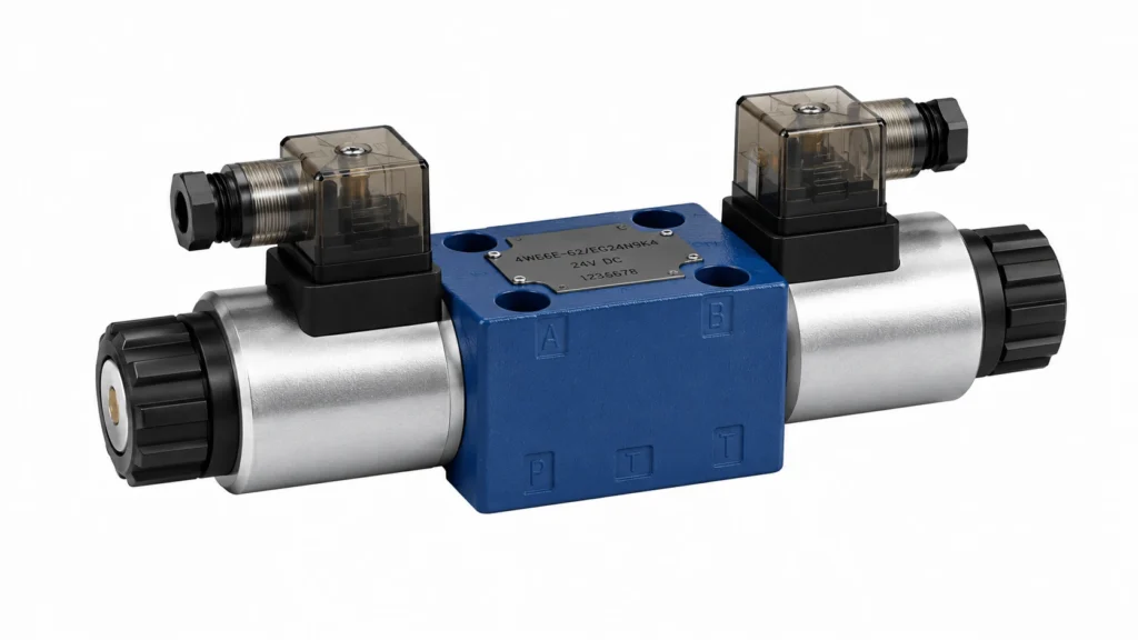
Proportional directional control valve
The most common type. A proportional directional valve controls both the direction and the amount of flow to an actuator, and therefore controls actuator speed and direction in one component. The spool has notches (often V-notches or triangular notches) machined into the lands so that the flow rises smoothly with spool travel instead of snapping open.
 
These valves are built to ISO 4401 / CETOP mounting patterns in sizes NG6, NG10, NG16, NG25, and NG32. Two solenoids drive the spool in two directions; a centering spring returns it to neutral when both are de-energized. Most modern versions accept an LVDT on one or both ends for closed-loop position control.
 
Rated flow follows the size: an NG6 valve is typically rated for 40–80 L/min, an NG10 for 80–300 L/min, an NG16 for 300–700 L/min, and NG25/NG32 for 700–1500 L/min and above — always quoted at 5 bar per control edge (see section 7.1).

Proportional pressure relief valves

Proportional pressure relief valves
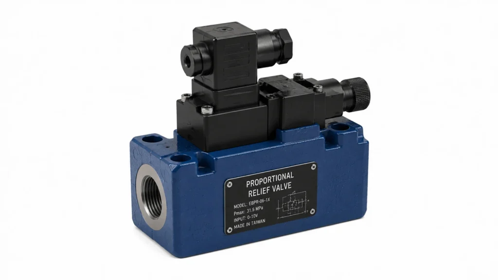
A proportional pressure relief valve replaces the manually adjusting screw on a conventional relief valve with a proportional solenoid. Command current sets the solenoid force, which sets the pilot pressure, which sets the system relief pressure.
 
The result is a system pressure you can program from a PLC — ramp it up for a press tonnage, drop it for a low-pressure hold, or profile it across a machine cycle.
 
Two architectures exist. The direct-operated version uses the solenoid to push a poppet directly; it is fast but limited to lower flows (pilot and small-system duty, typically up to a few L/min at 350 bar).
 
The pilot-operated version uses a small direct-operated proportional valve as the pilot stage and a main stage that amplifies the flow; this is what you use for main system pressure on a press or injection molding machine. Pilot-operated proportional relief valves handle 350 bar and hundreds of L/min, with hysteresis around 1–3% open-loop and under 1% with pressure feedback.
 

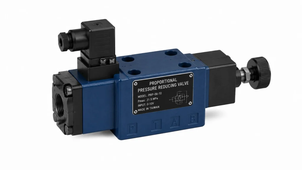
 Proportional pressure reducing valves
Proportional pressure reducing valves
These do for a branch circuit what a relief valve does for the whole system: they set a lower, regulated pressure in a sub-circuit while the main system runs higher.
 
A proportional reducing valve is the right choice when you have one pump feeding a high-pressure function and a lower-pressure function that both need to be programmable — for example, a clamping circuit at 80 bar alongside a working pressure of 250 bar.
 
The construction mirrors the relief valve: a proportional solenoid modulates a pilot stage, which controls the main reducing spool.
 
They are specified by regulated pressure range, maximum inlet pressure, and flow capacity, and they share the same electronics and feedback options as the relief family.
 

Proportional flow control valves

Proportional flow control valves
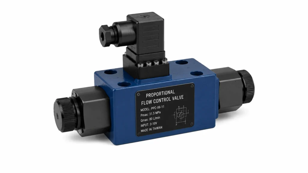
A proportional flow control valve meters flow independent of pressure fluctuations across the valve. The simplest form is a proportional throttle — just a proportional spool or poppet restricting flow, where flow still varies with pressure drop (Q ∝ √Δp).
 
For true flow control that holds a set flow regardless of load, you need a pressure-compensated version, which pairs the proportional throttle with a compensator spool that holds a constant Δp across the metering orifice.
 
The pressure-compensated 2-way proportional flow control is the workhorse of feed-speed circuits: a constant Δp across a proportional notch means the commanded spool position maps directly to a commanded flow, so the actuator speed tracks the input signal even as the load changes. These valves are common on machine tools, feed drives, and anywhere a steady feed rate matters more than peak speed.
 

High-response proportional valves

High-response proportional valves
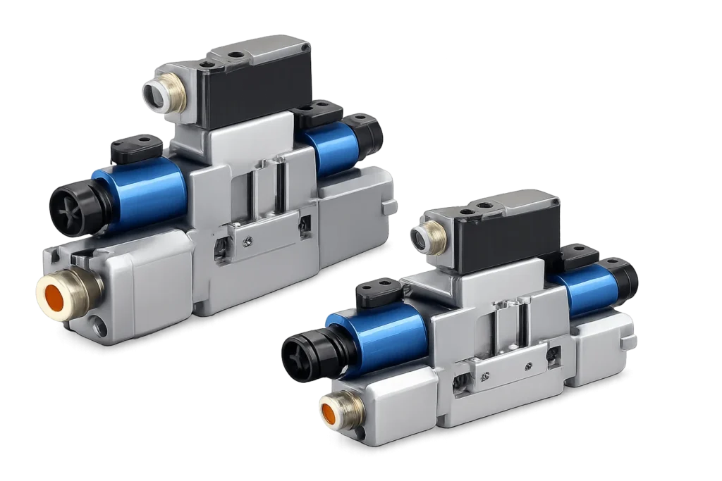
A high-response proportional valve is a closed-loop proportional valve engineered for fast dynamic response — typically a -3 dB frequency response of 40–80 Hz and step response under 10 ms.
 
They use a stronger solenoid, a lighter spool, integrated electronics mounted directly on the valve (OBE — on-board electronics), and a high-bandwidth LVDT loop.
 
These valves exist to close the gap with servo valves for applications that need servo-like response but cannot justify servo-like cleanliness and cost: injection molding injection/holding pressure control, die-casting shot control, active suspension, and fatigue test rigs.
 
If you are comparing a high-response proportional valve to a servo valve, the proportional valve will usually win on contamination tolerance, installation simplicity, and price, and lose on ultimate bandwidth and zero-overlap linearity.

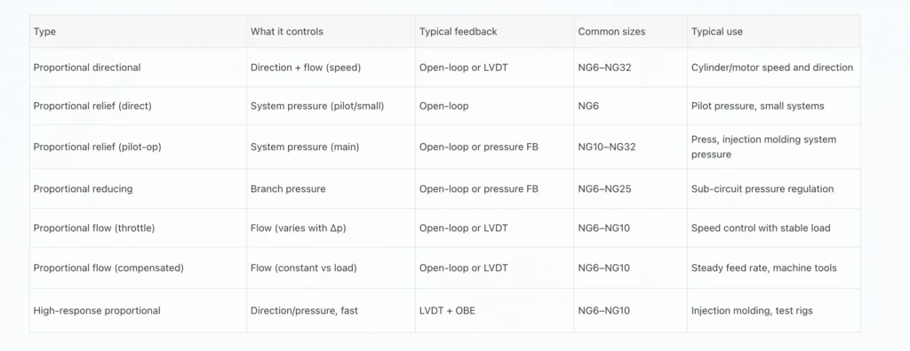
Proportional Valve Comparison Table

Proportional Valve Comparison Table

Key Specifications and What They Mean

Rated flow and the 5 bar/control edge convention

This is the specification that catches the most engineers, and getting it wrong sizes the valve wrong.

Manufacturers rate proportional directional valves at a pressure drop of 5 bar per control edge (sometimes 8 bar or 1 MPa, depending on the manufacturer — check the datasheet). A “4-way” valve has two control edges in series (meter-in and meter-out), so the total valve pressure drop at rated flow is about 10 bar.


When a catalog lists an NG10 valve at 160 L/min, that means 160 L/min at 5 bar per edge, not 160 L/min at whatever pressure you happen to be running.

If your system runs at 250 bar and you can only afford to lose 10 bar across the valve to keep efficiency reasonable, the rated flow on the datasheet is a reasonable target. If you can afford to lose 30 bar, the same valve will pass roughly √3, or about 1.7×, more flow — but the valve will saturate the spool stroke earlier and control authority drops.

The safe approach is to size so that the required flow at your allowable Δp is between 60% and 90% of the rated flow. Below 60%, the valve is oversized, and you waste resolution; above 90%, you run out of stroke under pressure spikes.

Hysteresis

Hysteresis is the difference in output (spool position, and therefore flow) for the same input signal depending on whether you approached it from above or below. It is caused by magnetic remanence in the solenoid and by static friction on the spool.

Open-loop proportional valves run 1–6% hysteresis. The driver card fights this with a dither signal — a small, high-frequency current ripple (typically 50–200 Hz at a few percent of rated current) that keeps the spool micro-moving so static friction never gets a chance to lock it. Dither trades a tiny bit of wear for a large cut in hysteresis. Too much dither and the valve hums and wears; too little and hysteresis climbs.

Closed-loop valves with an LVDT drop hysteresis below 0.3% because the position loop corrects for both magnetic and friction effects. If your application cannot tolerate 3% flow variation on a re-trace, you need the LVDT.

Dead band and compensation

Dead band is the band of the input signal around the center position where the spool does not move enough to open the metering notches. It exists because proportional directional valves use slight positive overlap to give a positive seal at neutral — without it, the valve would leak at rest and could not hold a load.

Dead band typically covers 10–20% of the input signal, sometimes more. It shows up as a “dead” zone in the middle of the joystick: push 15% and nothing happens, push 20% and the actuator jumps. The fix is electronic. The amplifier card applies a dead-band jump — when the input crosses zero, the output current skips ahead to the point where the notches just open, then resumes proportional control beyond that. Most drivers let you set the jump amplitude, and tuning it to the actual valve is part of commissioning.

Get the dead-band compensation wrong, and you get one of two symptoms: too little jump and the machine feels dead and then lurches off center; too much jump and the actuator creeps at zero command, which on a suspended load is a safety problem.

Response time and frequency response

Response time is quoted in two ways. Step response (t_63 or t_90) is how long the spool takes to reach 63% or 90% of a full-step command — typically 10–50 ms for a proportional valve, under 10 ms for a high-response version. Frequency response is the amplitude ratio and phase lag as a function of input frequency, plotted as a Bode plot; the -3 dB point is the common headline number, running 5–30 Hz for standard proportional valves and up to ~60 Hz for high-response units.

For most industrial speed and pressure control, a 10–30 ms step response is plenty. You need the high-response numbers when the valve is inside a fast control loop (injection pressure control during fill, active suspension, vibration suppression) where the valve has to track commands faster than the load dynamics. Buying more bandwidth than your loop needs is wasted money, and the faster valves are more sensitive to amplifier tuning and grounding.

Input signals and electronics

Proportional valves are driven by an amplifier card (or on-board electronics, OBE) that converts the command into PWM solenoid current. Command signals fall into three families:

  • Analog voltage (0–10 V, ±10 V) — simple, common, but susceptible to noise on long cable runs
  • Analog current (4–20 mA, 0–20 mA) — more noise-immune, the industrial default for long distances
  • Fieldbus / digital (CANopen, EtherCAT, PROFIBUS/PROFINET, IO-Link) — command, feedback, diagnostics, and parameterization over one bus; standard on modern integrated-electronics valves

The amplifier also generates the dither, the dead-band jump, and the ramp generators (separate ramp-up and ramp-down times so you can decelerate a load without shock). On a fieldbus valve, all of these are parameters you set over the bus; on a discrete amplifier card, they are potentiometers or DIP switches. Either way, the amplifier is where the valve actually gets tuned, and most field problems trace back to it, not to the hydraulics.

 Sizing a Proportional Valve

Sizing is a pressure-drop exercise, not a pressure-rating exercise. The valve has to pass your required flow at an acceptable pressure drop while leaving enough spool stroke for control.

  1. Determine required flow Q at the actuator — cylinder bore × speed, or motor displacement × rpm, converted to L/min.
  2. Decide the allowable valve pressure drop Δp_allow. For a 4-way valve with two control edges, total Δp is about 2 × per-edge. A common target is 5 bar per edge (10 bar total), matching the rated-flow convention.
  3. Calculate the required rated flow at the convention. Because flow scales with √Δp, the required rated flow = Q_required × √(5 / Δp_allow_per_edge). Pick the next size up whose rated flow covers this with a margin.
  4. Check that the required flow is 60–90% of the rated flow at your Δp. This keeps the operating point on the linear part of the flow curve.
  5. Verify pressure rating exceeds your maximum system pressure with a margin (typically 315 or 350 bar ratings cover most industrial duty).
  6. Decide open-loop vs closed-loop based on the control need (section 3.2), not the budget.
  7. Specify electronics: integrated OBE vs separate amplifier, and command signal (analog vs fieldbus) to match your controller.

Worked example: a press cylinder needs 200 L/min, and you allow 5 bar per edge. Required rated flow = 200 × √(5/5) = 200 L/min. An NG10 valve rated at 160 L/min is too small; an NG10 rated at 300 L/min, or an NG16 rated around 300 L/min, fits with the 200 L/min sitting at about 67% of rated flow — a good operating point.

Mounting Standards and Porting

Proportional directional valves follow the same mounting standards as conventional directional valves, which is one reason they drop into existing manifolds:

  • ISO 4401 / CETOP — the dominant standard for subplate-mounted directional valves, in sizes NG6 (ISO 4401-03), NG10 (ISO 4401-05), NG16 (ISO 4401-07), NG25 (ISO 4401-08), NG32 (ISO 4401-10)
  • NG6 and NG10 cover the majority of industrial applications; NG16 and above are for high-flow presses and plastics machinery
  • Cartridge proportional valves (logic elements with proportional pilot) for manifold-integrated high-flow circuits, using ISO 7368 cavities
  • In-line proportional valves for pressure and flow control, where subplate mounting is not practical

When retrofitting an on/off valve with a proportional valve of the same NG size, the bolt pattern and porting usually match. What does not match is the required pressure drop — a proportional valve of the same physical size typically needs more Δp to pass the same flow because of the metering notches. Plan for the extra loss or step up one size.

 Oil Cleanliness Requirements

Proportional valves tolerate more contamination than servo valves and less than on/off valves. The spool-to-bore clearances are similar to a standard directional valve, but the metering notches and the expectation of repeatable metering mean dirt shows up as hysteresis, drifting, and sticky response long before it causes a hard failure.

Recommended cleanliness targets:

Valve type Target ISO 4406 (1999) What it prevents
Open-loop proportional
19/17/14 minimum, 18/16/13 preferred
Spool sticking, notch silting
Closed-loop proportional (LVDT)
18/16/13
Same, plus LVDT bearing wear
High-response proportional
18/16/13, trending to 17/15/12
Protects high-bandwidth loop from silting
Servo valve (for reference)
15/13/11 or cleaner
Protects pilot-stage metering gaps
Silting (the gradual buildup of varnish and fine particles in the metering notches) is the silent killer of proportional valves. The valve does not fail; it just gets slower, drifts off zero, and loses its tuned dead-band compensation. A well-maintained proportional circuit runs a βₓ≥75 (preferably βₓ≥1000) return-line or pressure-line filter, monitors the oil, and changes fluid on condition, not on a calendar.

Common Proportional Valve Failures

Spool sticking/silting. The spool moves sluggishly or sticks at neutral. Cause: contamination buildup in the metering notches, often varnish from oxidized fluid. Symptom: the actuator does not respond to small inputs, then jumps when the input gets large enough to break the spool loose. Fix: flush the valve, clean or replace the fluid, verify the filtration β rating, and check fluid temperature (overheating accelerates oxidation).
 
Hysteresis drift. The same command gives different output depending on history. Cause: insufficient or excessive dither, aging solenoid, or loss of LVDT feedback in a closed-loop valve. Symptom: a position or speed that is not repeatable from cycle to cycle. Fix: check the amplifier dither setting, verify the LVDT signal, and re-run the auto-tune if the amplifier supports it.
Zero shift/offset. The actuator creeps, or the pressure drifts when the command is zero. Cause: dead-band compensation set too high, or positive-overlap spool worn so it no longer seals at neutral. Symptom: a cylinder that will not hold still, or a pressure that hunts at zero command. Fix: Reduce the dead-band jump, and if the spool is worn, the valve has to come out.
 
Sluggish or oscillatory response. Either the actuator lags the command badly, or it overshoots and hunts. Cause: ramp times set too long (sluggish) or loop gain set too high (oscillation), often combined with a poorly tuned LVDT loop. Symptom: the machine feels mushy or buzzes. Fix: re-tune the amplifier (ramp times, gain, and for closed-loop valves, the P/PID terms) using a step response on the bench.
 
Coil burnout. The solenoid fails open or overheats. Cause: overcurrent from a misconfigured amplifier, poor cooling (the valve mounted in a hot cabinet), or a shorted coil. Symptom: one direction stops working, or the coil is hot to the touch. Fix: verify amplifier current limit, improve cooling, and replace the coil.
 
Signal noise / erratic operation. The valve chatters or the actuator jitters. Cause: EMI on the command line, poor grounding, or analog signal wiring run alongside power cables. Symptom: fine jitter at all commands, worse at low speed. Fix: use shielded twisted-pair cable, ground the shield at one end, separate signal from power wiring, and prefer 4–20 mA or a fieldbus for long runs.

Troubleshooting Guide

Symptom Likely cause First check
No movement at small command, jump at larger
Dead band uncompensated or silting
Dead-band jump setting; oil cleanliness
Actuator creeps at zero command
Dead-band jump too high, or worn spool
Reduce jump; check neutral leakage
Slow, mushy response
Ramp times too long, low loop gain
Ramp and gain settings on amplifier
Buzzing / overshoot / hunting
Loop gain too high, LVDT loop mistuned
Reduce gain; re-tune PID
Non-repeatable speed cycle to cycle
Hysteresis (open-loop), weak dither
Increase dither; consider closed-loop valve
One direction dead
Coil open, amplifier channel failed
Coil resistance; amplifier output current
Valve hums audibly
Excessive dither
Reduce dither amplitude
Pressure drifts at zero command
Relief/reducing valve pilot silting
Flush; check fluid cleanliness and temperature
Jitter at all commands
EMI on signal line, poor grounding
Shielding, grounding, cable routing

How to Select the Right Proportional Valve

The selection is a sequence of five decisions, made in order:

  1. What are you controlling? Speed/direction → proportional directional. System pressure → proportional relief. Branch pressure → proportional reducing. Flow rate → proportional flow (pressure-compensated if load varies). This picks the family.
  2. Do you need feedback? Open-loop if the operator or a coarse sensor closes the loop. Closed-loop (LVDT) if you need to hold a position, a precise speed, or a tight pressure. Do not skip this step. It is the highest cost and performance lever.
  3. What flow and pressure? Size by the 5 bar/control edge convention (section 7.1), keeping the required flow at 60–90% of the rated. Confirm the pressure rating exceeds your max with a margin.
  4. What electronics? Integrated OBE saves wiring and gives fieldbus diagnostics, but locks you to one supplier’s ecosystem. Separate amplifier cards are more flexible and easier to swap. Match the command signal to your controller — analog for simple PLCs, fieldbus for modern controls.
  5. What environment? Mobile equipment needs robust connectors, vibration-rated coils, and often CANopen. Industrial machinery can use cabinet-mounted amplifiers and 4–20 mA. Washdown and hazardous-area duty need the right enclosure rating and approvals.

If you are replacing an on/off valve, expect to step up one NG size for the same flow, budget for the amplifier and wiring, and plan to tune the dead-band compensation and ramps on commissioning. The first proportional valve you commission will take longer than you think; the tenth will not.

Maintenance Best Practices

  • Hold oil cleanliness at ISO 4406 18/16/13 or better; monitor with regular fluid sampling, not a calendar
  • Use βₓ≥75 filtration minimum, βₓ≥1000 on the pressure or return line for closed-loop valves
  • Keep fluid temperature in the manufacturer’s band — typically 40–50°C operating, never above 60°C for sustained periods, because heat accelerates silting and oxidation
  • Periodically verify amplifier settings (dither, dead-band jump, ramps) have not drifted, especially after a card swap
  • Inspect connectors and coils for moisture, corrosion, and heat damage; a greenish coil terminal is a warning, not a cosmetic issue
  • For closed-loop valves, run the auto-tune routine after any mechanical work on the actuator or load
  • Keep a spare amplifier card and coil set for critical circuits; the hydraulic part rarely fails first
  • Log valve current and LVDT feedback, where the controller supports it; trend data catches silting and wear before they stop the machine

Industrial Applications

Injection molding machines are the single largest user of proportional valves. Injection speed, holding pressure, and back pressure all need programmable, repeatable control across the cycle, and high-response proportional directional and pressure valves are standard. The move to all-electric machines has not eliminated proportional hydraulics; tie-bar and clamping functions on large machines still run on proportional circuits.

Presses and metal forming use proportional pressure relief valves for programmable tonnage and proportional directional valves for ram speed control with soft approach and soft deceleration. The ability to ramp pressure and speed electronically is what lets a modern press run a fast low-tonnage cycle and a slow high-tonnage cycle without manual valve changes.

Mobile equipment — excavators, cranes, telehandlers, agricultural sprayers — runs proportional valves under joystick control for smooth boom and slew motion. CANopen and ISOBUS integration is standard, and contamination tolerance matters more than ultimate precision because the oil is rarely clean.

Marine hydraulics use proportional valves for winch and steering control, where stepless speed and programmable ramps protect the load and the crew. Corrosion-rated coils and connectors are mandatory.

Machine tools use pressure-compensated proportional flow controls for feed drives where a steady feed rate against a varying cutting load is the difference between a good part and a scrapped one.

Test stands and simulators use high-response proportional and servo valves for fatigue testing, flight-control loading, and component qualification. This is where the bandwidth and cleanliness investment pays off.

FAQ

What is a proportional valve used for?

A proportional valve is used when a hydraulic circuit needs stepless control of flow, pressure, or direction under electronic command, rather than the bang-bang switching of an on/off solenoid valve. Typical uses are cylinder speed and direction control on presses and mobile equipment, programmable system pressure on injection molding machines and presses, regulated branch pressure, and steady feed-rate control on machine tools. Anywhere an actuator needs to accelerate, hold, and decelerate smoothly under PLC or joystick command is a proportional valve application.

How does a proportional valve differ from a servo valve?

A proportional valve uses a proportional solenoid to move a spool with slight positive overlap, runs 1–6% hysteresis open-loop (under 0.3% closed-loop with an LVDT), and tolerates ISO 4406 18/16/13 oil. A servo valve uses a torque motor driving a flapper-nozzle or jet-pipe pilot stage, runs 0.1–0.5% hysteresis with zero or negative overlap, achieves 50–150+ Hz frequency response, and needs ISO 4406 15/13/11 or cleaner oil. Proportional valves are cheaper, more contamination-tolerant, and cover most industrial motion control; servo valves are reserved for high-bandwidth, high-precision loops where the cleanliness and cost are justified.

What is hysteresis in a proportional valve?

Hysteresis is the difference in valve output (spool position or flow) for the same input signal, depending on whether that signal was approached from a higher or lower value. It comes from magnetic remanence in the solenoid and static friction on the spool. Open-loop proportional valves typically show 1–6% hysteresis, reduced by a dither signal on the amplifier. Closed-loop valves with an LVDT position sensor correct hysteresis electronically and can hold it under 0.3%.

What is a dead band in a proportional valve, and how is it compensated?

Dead band is the range of input signal around the neutral position where the spool does not move far enough to open the metering notches, caused by the slight positive overlap that gives the valve a seal at rest. It typically covers 10–20% of the input signal. It is compensated electronically in the amplifier card with a dead-band jump — when the command crosses zero, the output current skips ahead to the point where the notches just open, then resumes proportional control. The jump amplitude is set during commissioning to match the specific valve.

Can a proportional valve be used in closed-loop control?

Yes. A closed-loop proportional valve adds an LVDT (or similar position transducer) that measures actual spool position and feeds it back to the amplifier, which corrects the solenoid current to hold the commanded position. This cuts hysteresis to under 0.3%, nearly eliminates dead band, and makes the valve suitable for position and precise speed control. Closed-loop proportional valves are distinct from servo valves; they use proportional solenoids and spool architecture rather than a flapper-nozzle pilot stage.

What oil cleanliness does a proportional valve need?

Open-loop proportional valves should run at ISO 4406 18/16/13 or better; closed-loop and high-response proportional valves should be held to 18/16/13 trending toward 17/15/12. For reference, servo valves need 15/13/11 or cleaner. Filtration should be βₓ≥75 minimum, βₓ≥1000 preferred on the pressure or return line. Poor cleanliness does not usually cause sudden failure; it causes silting in the metering notches, which shows up as drifting, sluggish small-signal response, and loss of the tuned dead-band compensation.

How do I size a proportional valve?

Size by pressure drop, not by pressure rating. Determine the required actuator flow, decide the allowable pressure drop per control edge (commonly 5 bar, matching the rated-flow convention), and pick a valve whose rated flow at that Δp puts your required flow at 60–90% of rated. Because flow scales with the square root of pressure drop, you can convert between Δp values with Q₂ = Q₁ × √(Δp₂/Δp₁). Verify the pressure rating exceeds your maximum with a margin, then choose open-loop or closed-loop based on the control need, not the budget.

Conclusion

A proportional valve is the component that turns a hydraulic circuit from a switch into a control system. It replaces the bang-bang of on/off solenoid valves with stepless, electronically commanded metering of flow, pressure, and direction, and it does it at a price and contamination tolerance that servo valves cannot match. The cost is electronics, tuning, and a more careful approach to sizing and oil cleanliness.
 
The decisions that determine whether a proportional circuit works are made before the valve is ordered: open-loop or closed-loop, sized by the 5 bar/control edge convention, electronics matched to the controller, and cleanliness held at ISO 4406 18/16/13. Get those right, and the valve tunes up in an afternoon. Get them wrong, and no amount of amplifier tweaking will rescue a machine that creeps, lurches, or will not hold a load.

Related Articles

Scroll to Top
Shoot Us An Email

Professional Manufacturer