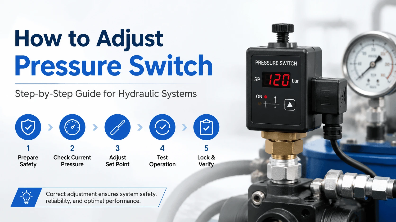
What is a Pressure Switch
| Type | Pressure Range | Typical Use | Adjustment Method |
|---|---|---|---|
Diaphragm/spring |
0.2 to 40 bar |
Low-pressure hydraulics, lubrication, water |
Range spring + differential screw |
Piston |
10 to 450 bar |
Medium-pressure hydraulics, HPU control |
Compressed spring with threaded actuator |
Bourdon tube |
20 to 700+ bar |
High-pressure hydraulic systems, test stands |
Limit switch on tube deflection |
Before You Adjust: Safety First
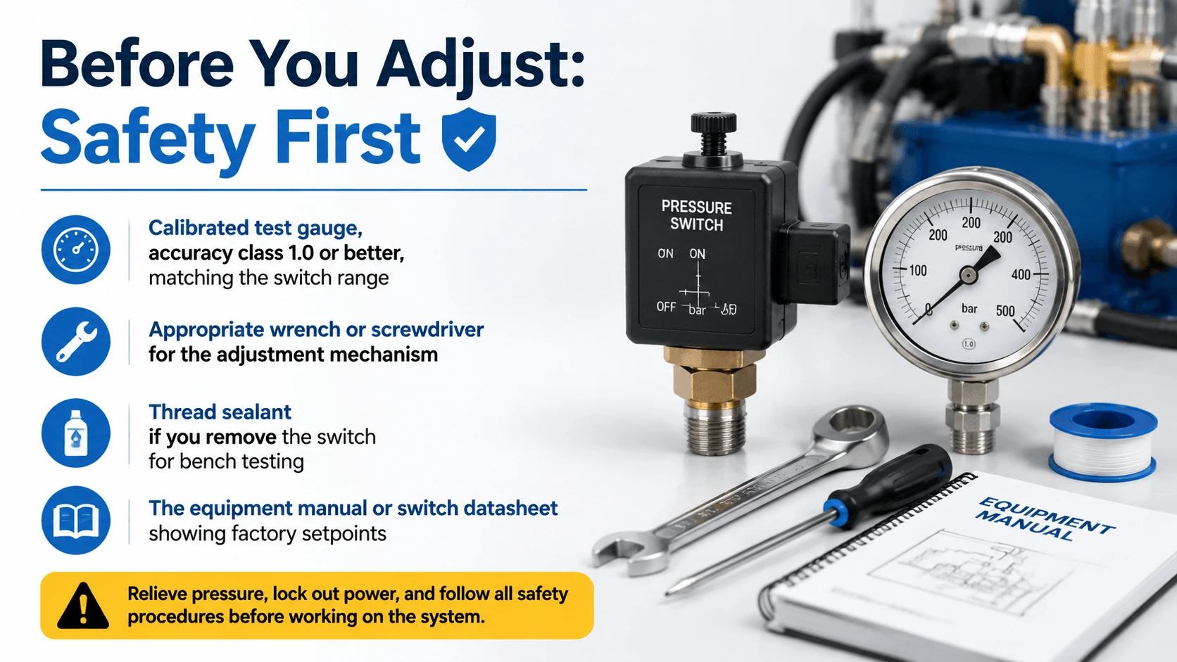
Before you touch any adjustment, isolate the unit electrically. Lock out the power source and tag it. Depressurize the system slowly through a bleed valve or downstream relief path. Even “dead” systems can hold trapped pressure behind check valves, so always crack a fitting at the switch location while wearing eye protection.
Gather your tools before starting:
- Calibrated test gauge, accuracy class 1.0 or better, matching the switch range
- Appropriate wrench or screwdriver for the adjustment mechanism
- Thread sealant, if you remove the switch for bench testing
- The equipment manual or switch datasheet showing factory setpoints
Never adjust a pressure switch by guesswork. You need a reference gauge reading actual system pressure at the moment the switch trips. The panel-mounted gauge ten feet away is not accurate enough for setpoint work.
How to Adjust Pressure Switch: Diaphragm/Spring Type
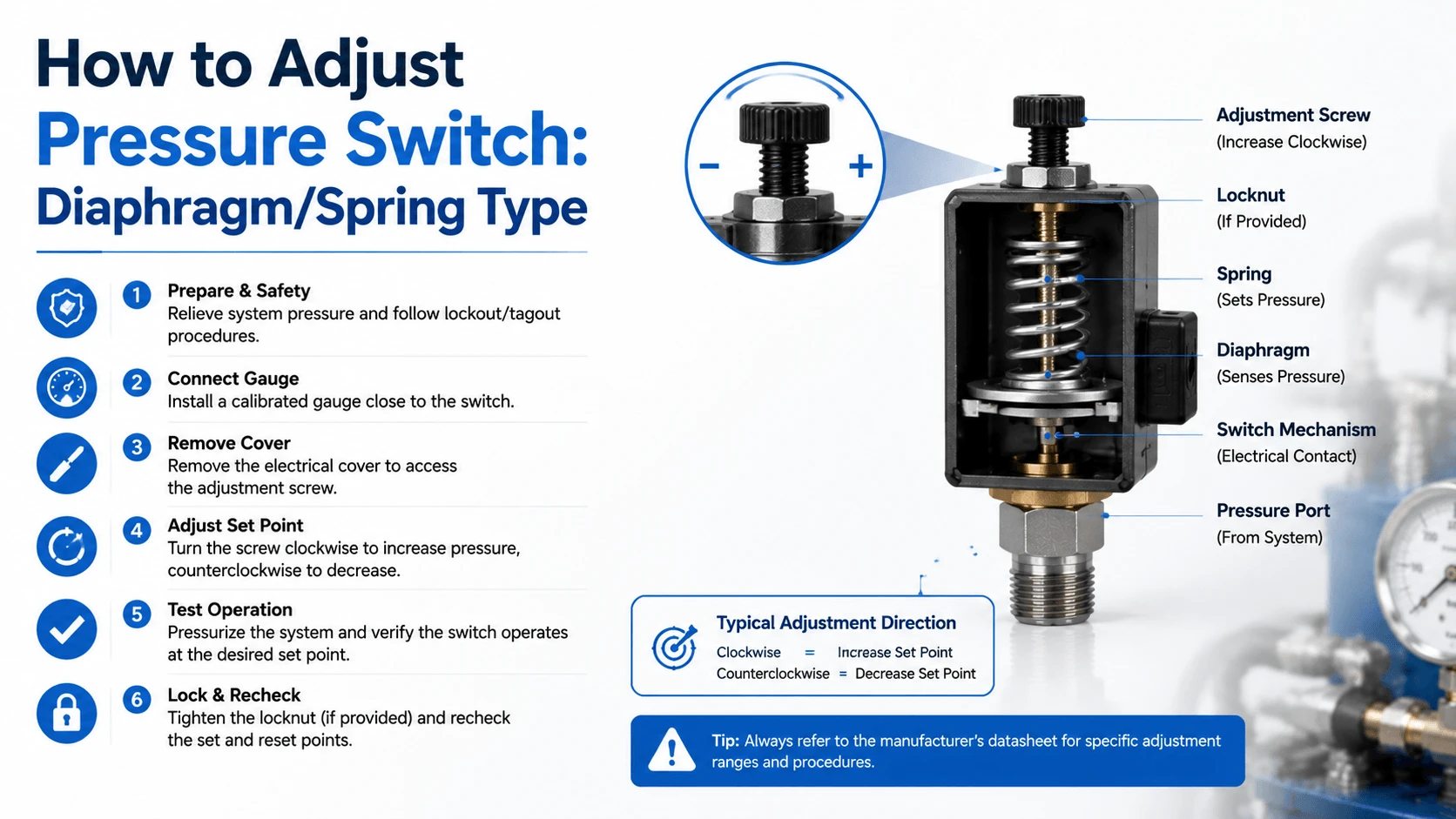
Diaphragm switches are the ones you see on small hydraulic power units, air compressors, and water pumps. They have two adjustments: a large range spring nut and a smaller differential screw. The range spring sets the cut-out (higher) pressure. The differential screw sets the gap between cut-in and cut-out, which controls the cut-in (lower) pressure.
Procedure
- Note the current cut-in and cut-out values if known. Check the equipment nameplate or manual.
- Connect your test gauge near the switch port.
- Pressurize the system slowly. Watch the gauge and note the exact pressure where the switch clicks open (cut-out) and closed (cut-in).
- To raise the cut-out pressure, compress the range spring by turning the main nut clockwise. One full turn typically adds 2 to 8 PSI, depending on the switch model. To lower it, turn counterclockwise.
- After each adjustment, cycle the pressure through the trip point at least twice. Let the mechanism stabilize for a few seconds between cycles.
- If the cut-in pressure also needs changing, adjust the differential screw. Turning it clockwise widens the differential (lowers the cut-in). Counter-clockwise narrows it (raises cut-in).
- Once both values are correct, tighten the locknut if equipped. Some models use a sealing compound instead of a locknut. Do not overtighten or you will shift the setpoint you just set.
The key when you adjust pressure switch units of this type is to make small increments. A quarter-turn can move the trip point by 1 to 2 PSI on sensitive models. Crank the nut three full turns, and you will overshoot by a wide margin.
How to Adjust Pressure Switch: Piston Type
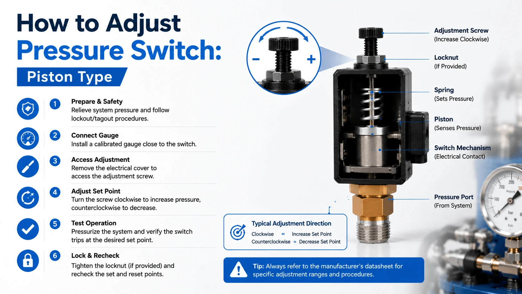
Piston-type switches handle higher pressures, from about 100 bar up to 450 bar in standard versions. Instead of a flexible diaphragm, a hardened steel piston moves directly against the spring. When you adjust pressure switch models of this kind, you change the spring compression via a threaded plunger or an external screw acting on the spring seat.
Procedure
- Verify system pressure with a calibrated gauge at the switch location.
- Locate the adjustment. On most piston switches, it is a screw on top of the bonnet or a hex nut on the spring housing. Refer to the manufacturer’s diagram.
- Determine the direction. For nearly all piston switches, clockwise rotation increases setpoint by adding spring preload. Counter-clockwise decreases it. Confirm this in the datasheet because reverse-acting models exist.
- Make adjustments in small steps. For a switch set around 200 bar, start with one-eighth turn increments. Cycle pressure and check the trip point after each change.
- Allow time for stabilization. Piston switches have more internal friction than diaphragm types. The trip point can shift slightly after pressure stabilizes.
- At the target setpoint, apply the thread locker or tighten the locknut per the manufacturer’s torque spec. Vibration from pumps and motors will loosen an unsecured screw within weeks.
Piston switches generally have a fixed differential of 10 to 15% of the setpoint, determined by the snap-action mechanism geometry. If you need independent control over both cut-in and cut-out on a high-pressure system, use two separate switches or a dual-switch controller rather than trying to modify the internal differential.
How to Adjust Pressure Switch: Bourdon Tube Type
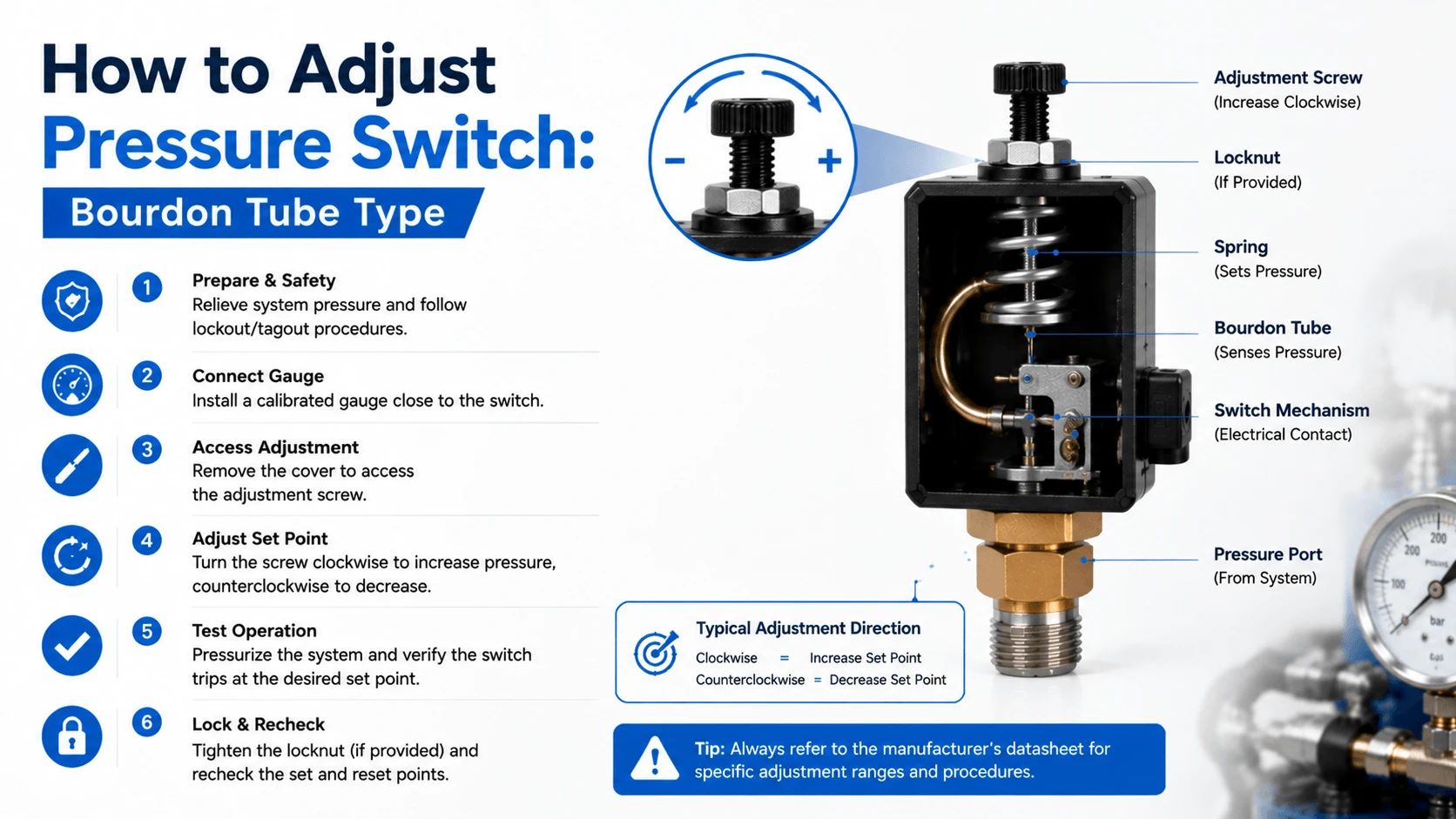
Bourdon tube switches show up on high-pressure hydraulic test stands, waterjet cutting systems, and heavy press applications above 400 bar. The curved tube straightens under pressure, and a mechanical linkage moves a contact block past a snap-action switch. Adjustment usually means moving the position of that switch relative to the linkage travel.
Procedure
- Remove the cover (if equipped) to expose the microswitch and adjustment screws.
- Identify the setpoint screw. It typically moves the switch mounting bracket along an arc that follows the tube’s motion path.
- Pressurize slowly to the desired trip point using a hand pump or controlled system pressure.
- At the target pressure, turn the adjustment until the switch just clicks. Back off slightly and approach again to find the exact trip position.
- Depressurize and repressurize to verify repeatability within plus or minus 1% of the setpoint. Replace the cover and install a tamper-evident seal wire if required.
Bourdon tube switches are less forgiving of overadjustment than other types. The linkage can bind, or the tube can be stressed beyond its elastic limit if you force the mechanism against the stop. Move the adjustment slowly and never use pliers on the screw head.
Understanding Differential and Deadband
Differential, also called deadband or span, is the pressure difference between the cut-out (trip) point and the cut-in (reset) point. When you adjust the pressure switch differential, you control how much the pressure must drop before the switch resets itself.
Why does this matter? A narrow differential causes rapid cycling. The switch trips at 200 bar, resets at 195 bar, the pump builds back to 200 bar, and the cycle repeats every few seconds.
This burns out the contact surfaces, heats the pump motor, and eventually destroys the switch mechanism. A wide differential means the switch resets at a much lower pressure, which may be fine for a simple alarm but unacceptable for a control sequence that needs tight regulation.
Good practice for hydraulic systems:
| Application | Recommended Differential |
|---|---|
Pump unload/reload control |
15-25% of setpoint |
High-pressure alarm |
Not critical (alarm only) |
Low-pressure shutdown |
5-10% of setpoint |
Sequence valve interlock |
10-15% of setpoint |
Filter clogging indicator |
Fixed value (per filter spec) |
When you adjust pressure switch settings, always check both the trip and reset pressures. A switch that trips at the right pressure but resets 5 bar too low will still cause problems in a control loop.
Verifying Your Adjustment
Adjustment means nothing without verification. After you adjust pressure switch hardware, confirm the trip and reset points with these steps:
- Slowly increase system pressure from zero. Record the exact trip pressure where the contact changes state.
- Slowly decrease pressure. Record the exact reset pressure.
- Repeat the cycle three times. All three readings should agree within plus or minus 1% of the nominal setpoint or the switch’s stated repeatability spec, whichever is worse.
- Compare results to target values. If outside tolerance, readjust and retest.
- Document final values on the equipment maintenance log. Include date, technician name, old setpoint, new setpoint, and gauge serial number used for testing.
For critical applications like safety interlocks or high-pressure shutdowns, consider removing the switch and testing it on a calibrated pressure comparator or hand pump bench. System-mounted testing picks up vibration, temperature effects, and line pulsation that can mask the true switch behavior.
Common Adjustment Mistakes
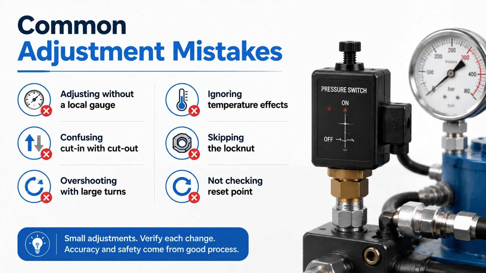
Adjusting without a local gauge
Confusing cut-in with cut-out
Overshooting with large turns
Ignoring temperature effects
Skipping the locknut
Not checking reset point
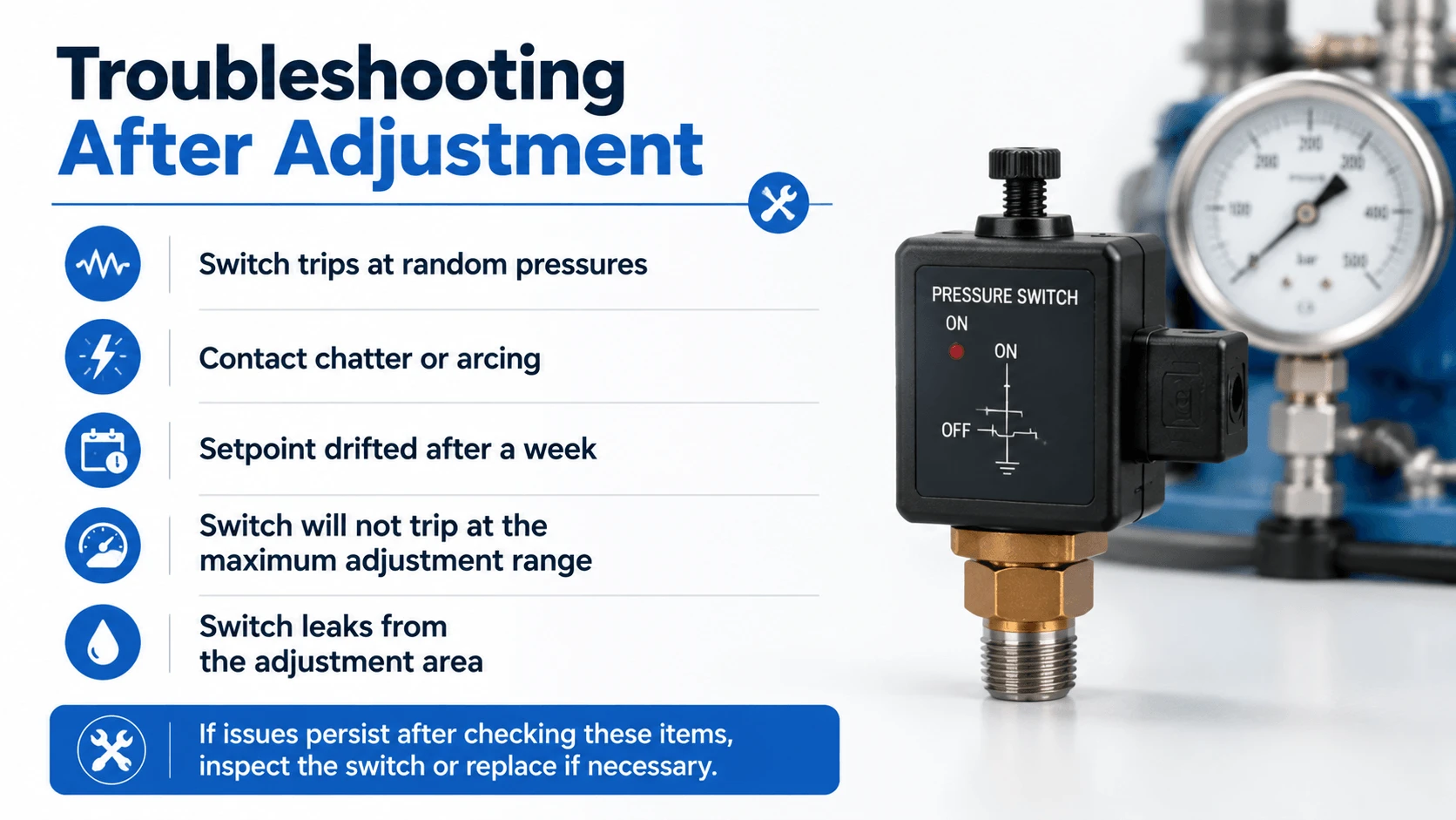
Troubleshooting After Adjustment